|
#include <windows.h>

#define MYWNDCLASS  "Engine3D_Class"
#define MYWNDTITLE  "Engine3D"
#define WIDTH       200     // 画面の横のサイズ
#define HEIGHT      150     // 画面の縦のサイズ
#define COLOR_BIT   24      // 作業用DIBの色深度
#define WIDTHBYTES(bits)    ((((bits) + 31)>>5)<<2) // 4倍バイト境界幅を求める

HBITMAP ghBmpWork = NULL;
BYTE    *gpBitsWork = NULL;

LRESULT CALLBACK ProcWnd(HWND hWnd, UINT uMsg, WPARAM wParam, LPARAM lParam);
void Create_Work_Dib();
void M_Create();
void M_Paint(HDC hDC);
void M_Close();

int WINAPI WinMain(HINSTANCE hInst,HINSTANCE hInstPrev,LPSTR lpCmdLine,int nCmdShow)
{
    MSG        msg;
    WNDCLASSEX wc;
    HWND       hWnd;

    ZeroMemory(&wc, sizeof(wc));
    wc.cbSize           = sizeof(WNDCLASSEX);
    wc.lpfnWndProc      = (WNDPROC)ProcWnd;
    wc.hInstance        = hInst;
    wc.hIcon            = LoadIcon(NULL, IDI_APPLICATION);
    wc.hCursor          = LoadCursor(NULL, IDC_ARROW);
    wc.hbrBackground    = (HBRUSH)(COLOR_WINDOW+1);
    wc.lpszMenuName     = NULL;
    wc.lpszClassName    = MYWNDCLASS;
    RegisterClassEx(&wc);

    DWORD   dwStyle = WS_OVERLAPPED | WS_SYSMENU | WS_MINIMIZEBOX | WS_CAPTION | WS_VISIBLE;
    RECT    rc = {0, 0, WIDTH, HEIGHT};
    AdjustWindowRectEx(&rc, dwStyle, FALSE, NULL);

    hWnd = CreateWindowEx(0,
                MYWNDCLASS,
                MYWNDTITLE,
                dwStyle,
                CW_USEDEFAULT, CW_USEDEFAULT, rc.right - rc.left, rc.bottom - rc.top,
                NULL,
                NULL,
                hInst,
                NULL);

    while (GetMessage(&msg, NULL, 0, 0)) {
        TranslateMessage(&msg);
        DispatchMessage(&msg);
    }
    return msg.wParam;
}

LRESULT CALLBACK ProcWnd(HWND hWnd, UINT uMsg, WPARAM wParam, LPARAM lParam)
{
    switch (uMsg)
    {
    case WM_CREATE:
        M_Create();
        return 0;
    case WM_PAINT:
        {
            HDC         hDC,hDCcp;
            HBITMAP     hBmpPre;
            PAINTSTRUCT ps;
            hDC = BeginPaint(hWnd,&ps);
            Create_Work_Dib();
            if(ghBmpWork){
                hDCcp = CreateCompatibleDC(hDC);
                hBmpPre = (HBITMAP) SelectObject(hDCcp, ghBmpWork);
                HRGN hrgn = CreateRectRgn(0, 0, WIDTH, HEIGHT);
                SelectClipRgn(hDCcp, hrgn);
                DeleteObject(hrgn);
                M_Paint(hDCcp);
                BitBlt(hDC, 0, 0, WIDTH, HEIGHT, hDCcp, 0, 0, SRCCOPY);
                SelectObject(hDCcp, hBmpPre);
                SelectClipRgn(hDCcp, (HRGN) NULL);
                DeleteDC(hDCcp);
                DeleteObject(ghBmpWork);
            }
            EndPaint(hWnd,&ps);
        }
        return 0;
    case WM_CLOSE:
        M_Close();
        DestroyWindow(hWnd);
        PostQuitMessage(0);
        return 0;
    default:
        break;
    }
    return DefWindowProc(hWnd, uMsg, wParam, lParam);
}

// 作業用DIBの作成
void Create_Work_Dib()
{
    BITMAPINFO  bmi;

    ZeroMemory(&bmi, sizeof(bmi));
    bmi.bmiHeader.biSize            = sizeof(BITMAPINFOHEADER);
    bmi.bmiHeader.biWidth           = WIDTH;
    bmi.bmiHeader.biHeight          = -HEIGHT;
    bmi.bmiHeader.biPlanes          = 1;
    bmi.bmiHeader.biBitCount        = COLOR_BIT;
    bmi.bmiHeader.biCompression     = BI_RGB;

    ghBmpWork = (HBITMAP) CreateDIBSection(NULL, &bmi, DIB_RGB_COLORS, (VOID **)&gpBitsWork, NULL, 0);

    int workSize = WIDTHBYTES(WIDTH * COLOR_BIT) * HEIGHT;
    ZeroMemory(gpBitsWork, workSize);
}// Create_Work_Dib

// 初期化
void M_Create()
{
}// M_Create

// 描画
void M_Paint(HDC hDC)
{
}// M_Paint

// 終了処理
void M_Close()
{
}// M_Close
|
|
|
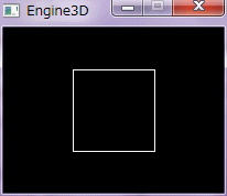
3D座標を2D座標に変換する事を投象と呼び、平行投象と透視投象がある。
平行投象には、遠近感が出ないが、透視投象には出る。 Direct3Dでは、プロジェクション行列変換が、これに該当し、 平行投象は正射影、透視投象はパースペクティブ射影と呼ばれている。 立方体を平行投象でワイヤーフレーム表示する。 以下のコードを上のコードに置換、または追加する。 参考資料:コンピュータ・グラフィックス J.D.FOLEY/A.VAN DAM著 日本コンピュータ協会 p.282 〜 p.283
typedef struct{
    float   x;
    float   y;
    float   z;
}VEC3,*LPVEC3;

typedef struct{
    VEC3    v[8];       // 頂点座標
    int     f[6][4];    // 各面の頂点番号
}MODEL,*LPMODEL;

MODEL   gmCube;

void Create_Cube();
POINT Ortho(float d_ortho, VEC3 pos, POINT move);
void M_Create();
void M_Paint(HDC hDC);

// 立方体の作成
void Create_Cube()
{
    VEC3    v[8]    =   {{0.5f,0.5f,-0.5f},{0.5f,0.5f,0.5f},{-0.5f,0.5f,0.5f},
                        {-0.5f,0.5f,-0.5f},{0.5f,-0.5f,-0.5f},{0.5f,-0.5f,0.5f},
                        {-0.5f,-0.5f,0.5f},{-0.5f,-0.5f,-0.5f}};
    int     f[6][4] =   {{3,2,1,0},{0,1,5,4},{1,2,6,5},{2,3,7,6},{3,0,4,7},{4,5,6,7}};
    memcpy(gmCube.v, v, sizeof(gmCube.v));
    memcpy(gmCube.f, f, sizeof(gmCube.f));
}// Create_Cube

// 平行投象
POINT Ortho(float d_ortho, VEC3 pos, POINT move)
{
    POINT pt;
    pt.x = (long)( pos.x * d_ortho) + move.x;
    pt.y = (long)(-pos.y * d_ortho) + move.y;
    return pt;
}// Ortho

// 初期化
void M_Create()
{
    Create_Cube();
}// M_Create

// 描画
void M_Paint(HDC hDC)
{
    int         i,j,index;
    POINT       pt[4];
    const float d_ortho = HEIGHT / 2;               // 平行投象での拡大率
    const POINT offset = {WIDTH / 2, HEIGHT / 2};   // 投象後の二次元座標の平行移動幅
    const HPEN  hpen = (HPEN) GetStockObject(WHITE_PEN);

    HPEN hpenPre = (HPEN) SelectObject(hDC, hpen);
    for(i=0; i<6; i++){
        for(j=0; j<4; j++){
            index = gmCube.f[i][j];
            pt[j] = Ortho(d_ortho, gmCube.v[index], offset);

        }
        Polyline(hDC, pt, 4);
    }
    SelectObject(hDC, hpenPre);
}// M_Paint
|

|
|
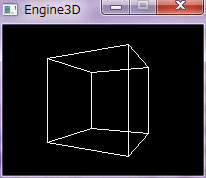
立方体を透視投象でワイヤーフレーム表示する。
平行投象と違い、遠近感(立体感)が出ている。 透視投象には、視点のZ座標情報が必要となる。 以下のコードを上のコードに置換、または追加する。 透視投象のコードを見ると、視点から離れるほど頂点座標が小さくなるのが分かる。 参考資料:3Dネットワークゲーム プログラミングガイド インフィニティ著 秀和システムp.15 〜 p.16
POINT Perspect(float d_perspect, VEC3 pos, float look_z, POINT move);
void M_Paint(HDC hDC);

// 透視投象
POINT Perspect(float d_perspect, VEC3 pos, float look_z, POINT move)
{
    POINT pt;
    if(pos.z == look_z){
        pt.x = move.x;
        pt.y = move.y;
    }
    else{
        pt.x = (long)( pos.x * d_perspect / (pos.z - look_z)) + move.x;
        pt.y = (long)(-pos.y * d_perspect / (pos.z - look_z)) + move.y;
    }
    return pt;
}// Perspect

// 描画
void M_Paint(HDC hDC)
{
    int         i,j,index;
    POINT       pt[4];
    const float d_perspect = HEIGHT;                // 透視投象での投影するスクリーンと視点の距離
    const float look_z = 2.0f;                      // 視点のZ座標
    const POINT offset = {WIDTH / 2, HEIGHT / 2};   // 投象後の二次元座標の平行移動幅
    const HPEN  hpen = (HPEN) GetStockObject(WHITE_PEN);

    HPEN hpenPre = (HPEN) SelectObject(hDC, hpen);
    for(i=0; i<6; i++){
        for(j=0; j<4; j++){
            index = gmCube.f[i][j];
            pt[j] = Perspect(d_perspect, gmCube.v[index], look_z, offset);

        }
        Polyline(hDC, pt, 4);
    }
    SelectObject(hDC, hpenPre);
}// M_Paint
|
|
|
視点の位置を変えるには、ビュー行列を設定し、頂点座標に適用する。
以下のコードを上のコードに置換、または追加する。 参考資料:Microsoft DirectX9 ヘルプ
#include <math.h>

typedef struct{
    union{
        struct{
            float   _11, _12, _13, _14;
            float   _21, _22, _23, _24;
            float   _31, _32, _33, _34;
            float   _41, _42, _43, _44;
        };
        float m[4][4];
    };
}MTRX,*LPMTRX;

VEC3 Vec3Sub(VEC3 v1, VEC3 v2);
VEC3 Vec3Normalize(VEC3 vin);
VEC3 Vec3Cross(VEC3 v1, VEC3 v2);
MTRX MtrxView(VEC3 v_look, VEC3 v_lookat, VEC3 v_lookup);
VEC3 MtrxVec3(VEC3 v, MTRX mt);
void M_Paint(HDC hDC);

// ベクトルの引き算
VEC3 Vec3Sub(VEC3 v1, VEC3 v2)
{
    VEC3    vout;
    vout.x = v1.x  - v2.x;
    vout.y = v1.y  - v2.y;
    vout.z = v1.z  - v2.z;
    return vout;
}// Vec3Sub

// 単位ベクトル
VEC3 Vec3Normalize(VEC3 vin)
{
    VEC3    vout;
    float   len = (float) sqrt(vin.x * vin.x + vin.y * vin.y + vin.z * vin.z);
    if(len == 0.0f){
        vout.x = 0.0f;
        vout.y = 0.0f;
        vout.z = 0.0f;
    }
    else{
        vout.x = vin.x / len;
        vout.y = vin.y / len;
        vout.z = vin.z / len;
    }
    return vout;
}// Vec3Normalize

// 外積
VEC3 Vec3Cross(VEC3 v1, VEC3 v2)
{
    VEC3    vout;
    vout.x = v1.y * v2.z - v1.z * v2.y;
    vout.y = v1.z * v2.x - v1.x * v2.z;
    vout.z = v1.x * v2.y - v1.y * v2.x;
    return vout;
}// Vec3Cross

// ビュー行列
MTRX MtrxView(VEC3 v_look, VEC3 v_lookat, VEC3 v_lookup)
{
    MTRX mt;
    VEC3 v_x,v_y,v_z;
    v_z = Vec3Normalize(Vec3Sub(v_lookat, v_look));
    v_x = Vec3Normalize(Vec3Cross(v_lookup, v_z));
    v_y = Vec3Cross(v_z, v_x);
    mt._11 = v_x.x;
    mt._12 = v_y.x;
    mt._13 = v_z.x;
    mt._14 = 0;
    mt._21 = v_x.y;
    mt._22 = v_y.y;
    mt._23 = v_z.y;
    mt._24 = 0;
    mt._31 = v_x.z;
    mt._32 = v_y.z;
    mt._33 = v_z.z;
    mt._34 = 0;
    mt._41 = 0;
    mt._42 = 0;
    mt._43 = 0;
    mt._44 = 1;
    return mt;
}// MtrxView

// 行列を座標に適用
VEC3 MtrxVec3(VEC3 v, MTRX mt)
{
    VEC3 v2;
    v2.x = v.x * mt._11 + v.y * mt._21 + v.z * mt._31 + mt._41;
    v2.y = v.x * mt._12 + v.y * mt._22 + v.z * mt._32 + mt._42;
    v2.z = v.x * mt._13 + v.y * mt._23 + v.z * mt._33 + mt._43;
    return v2;
}// MtrxVec3

// 描画
void M_Paint(HDC hDC)
{
    int         i,j;
    POINT       pt[4];
    const float d_perspect = HEIGHT;                // 透視投象での投影するスクリーンと視点の距離
    const POINT offset = {WIDTH / 2, HEIGHT / 2};   // 投象後の二次元座標の平行移動幅
    const VEC3  pos_look = {1.0f, 0.0f, -2.0f};     // 視点の位置
    const VEC3  pos_lookat = {0, 0, 0};             // 注視点の位置
    const VEC3  v_lookup = {0, 1, 0};               // 視点の上向き
    const HPEN  hpen = (HPEN) GetStockObject(WHITE_PEN);

    MTRX mt_view = MtrxView(pos_look, pos_lookat, v_lookup);

    HPEN hpenPre = (HPEN) SelectObject(hDC, hpen);
    for(i=0; i<6; i++){
        for(j=0; j<4; j++){
            int  index = gmCube.f[i][j];
            VEC3 v = MtrxVec3(gmCube.v[index], mt_view);
            pt[j] = Perspect(d_perspect, v, pos_look.z, offset);
        }
        Polyline(hDC, pt, 4);
    }
    SelectObject(hDC, hpenPre);
}// M_Paint
|
|
|
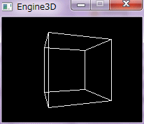
モデルの回転・移動・拡大縮小は、ワールド行列で行う。
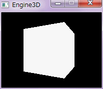
モデルは、ローカル空間(モデル空間)からワールド行列変換によってワールド空間に移行し、 ビュー行列変換によってワールド空間からビュー空間(カメラ空間)に移行し、 プロジェクション行列変換によってビュー空間からスクリーン空間へ移行する。 行列も、ワールド行列×ビュー行列×プロジェクション行列の順に掛け合わせる。 以下のコードを上のコードに置換、または追加する。 Polyline() をPolygon() に書き換えると右図のような面描画になるが、 濃淡がないため、立体感が出ない。
LRESULT CALLBACK ProcWnd(HWND hWnd, UINT uMsg, WPARAM wParam, LPARAM lParam);
MTRX MtrxIdent();
MTRX MtrxRotY(float radian);
MTRX MtrxMult(MTRX mt1, MTRX mt2);
void M_Paint(HDC hDC);

LRESULT CALLBACK ProcWnd(HWND hWnd, UINT uMsg, WPARAM wParam, LPARAM lParam)
{
    switch (uMsg)
    {
    case WM_CREATE:
        M_Create();
        SetTimer(hWnd, 1, 100, NULL);
        return 0;
    case WM_TIMER:
        InvalidateRect(hWnd, NULL, FALSE);  // 再描画
        break;
    case WM_PAINT:
        {
            HDC         hDC,hDCcp;
            HBITMAP     hBmpPre;
            PAINTSTRUCT ps;
            hDC = BeginPaint(hWnd,&ps);
            Create_Work_Dib();
            if(ghBmpWork){
                hDCcp = CreateCompatibleDC(hDC);
                hBmpPre = (HBITMAP) SelectObject(hDCcp, ghBmpWork);
                HRGN hrgn = CreateRectRgn(0, 0, WIDTH, HEIGHT);
                SelectClipRgn(hDCcp, hrgn);
                DeleteObject(hrgn);
                M_Paint(hDCcp);
                BitBlt(hDC, 0, 0, WIDTH, HEIGHT, hDCcp, 0, 0, SRCCOPY);
                SelectObject(hDCcp, hBmpPre);
                SelectClipRgn(hDCcp, (HRGN) NULL);
                DeleteDC(hDCcp);
                DeleteObject(ghBmpWork);
            }
            EndPaint(hWnd,&ps);
        }
        return 0;
    case WM_CLOSE:
        KillTimer(hWnd, 1);
        M_Close();
        DestroyWindow(hWnd);
        PostQuitMessage(0);
        return 0;
    default:
        break;
    }
    return DefWindowProc(hWnd, uMsg, wParam, lParam);
}

// 単位行列
MTRX MtrxIdent()
{
    MTRX mt = { 1,0,0,0,
                0,1,0,0,
                0,0,1,0,
                0,0,0,1};
    return mt;
}// MtrxIdent

// 行列のY軸回転
MTRX MtrxRotY(float radian)
{
    MTRX mt = MtrxIdent();
    mt._11 = (float)  cos(radian);
    mt._13 = (float) -sin(radian);
    mt._31 = (float)  sin(radian);
    mt._33 = (float)  cos(radian);
    return mt;
}// MtrxRotY

// 行列連結
MTRX MtrxMult(MTRX mt1, MTRX mt2)
{
    MTRX mt;
    mt._11 = mt1._11 * mt2._11 + mt1._12 * mt2._21 + mt1._13 * mt2._31 + mt1._14 * mt2._41;
    mt._12 = mt1._11 * mt2._12 + mt1._12 * mt2._22 + mt1._13 * mt2._32 + mt1._14 * mt2._42;
    mt._13 = mt1._11 * mt2._13 + mt1._12 * mt2._23 + mt1._13 * mt2._33 + mt1._14 * mt2._43;
    mt._14 = mt1._11 * mt2._14 + mt1._12 * mt2._24 + mt1._13 * mt2._34 + mt1._14 * mt2._44;
    mt._21 = mt1._21 * mt2._11 + mt1._22 * mt2._21 + mt1._23 * mt2._31 + mt1._24 * mt2._41;
    mt._22 = mt1._21 * mt2._12 + mt1._22 * mt2._22 + mt1._23 * mt2._32 + mt1._24 * mt2._42;
    mt._23 = mt1._21 * mt2._13 + mt1._22 * mt2._23 + mt1._23 * mt2._33 + mt1._24 * mt2._43;
    mt._24 = mt1._21 * mt2._14 + mt1._22 * mt2._24 + mt1._23 * mt2._34 + mt1._24 * mt2._44;
    mt._31 = mt1._31 * mt2._11 + mt1._32 * mt2._21 + mt1._33 * mt2._31 + mt1._34 * mt2._41;
    mt._32 = mt1._31 * mt2._12 + mt1._32 * mt2._22 + mt1._33 * mt2._32 + mt1._34 * mt2._42;
    mt._33 = mt1._31 * mt2._13 + mt1._32 * mt2._23 + mt1._33 * mt2._33 + mt1._34 * mt2._43;
    mt._34 = mt1._31 * mt2._14 + mt1._32 * mt2._24 + mt1._33 * mt2._34 + mt1._34 * mt2._44;
    mt._41 = mt1._41 * mt2._11 + mt1._42 * mt2._21 + mt1._43 * mt2._31 + mt1._44 * mt2._41;
    mt._42 = mt1._41 * mt2._12 + mt1._42 * mt2._22 + mt1._43 * mt2._32 + mt1._44 * mt2._42;
    mt._43 = mt1._41 * mt2._13 + mt1._42 * mt2._23 + mt1._43 * mt2._33 + mt1._44 * mt2._43;
    mt._44 = mt1._41 * mt2._14 + mt1._42 * mt2._24 + mt1._43 * mt2._34 + mt1._44 * mt2._44;
    return mt;
}// MtrxMult

// 描画
void M_Paint(HDC hDC)
{
    int         i,j;
    POINT       pt[4];
    const float d_perspect = HEIGHT;                // 透視投象での投影するスクリーンと視点の距離
    const POINT offset = {WIDTH / 2, HEIGHT / 2};   // 投象後の二次元座標の平行移動幅
    const VEC3  pos_look = {1.0f, 0.0f, -2.0f};     // 視点の位置
    const VEC3  pos_lookat = {0, 0, 0};             // 注視点の位置
    const VEC3  v_lookup = {0, 1, 0};               // 視点の上向き
    const HPEN  hpen = (HPEN) GetStockObject(WHITE_PEN);
    static int  roll_y = 0;                         // 回転角度

    MTRX mt_view  = MtrxView(pos_look, pos_lookat, v_lookup);
    MTRX mt_world = MtrxRotY(roll_y * 3.14f / 180);
    MTRX mt_all   = MtrxMult(mt_world, mt_view);

    HPEN hpenPre = (HPEN) SelectObject(hDC, hpen);
    for(i=0; i<6; i++){
        for(j=0; j<4; j++){
            int  index = gmCube.f[i][j];
            VEC3 v = MtrxVec3(gmCube.v[index], mt_all);
            pt[j] = Perspect(d_perspect, v, pos_look.z, offset);
        }
        Polyline(hDC, pt, 4);
    }
    SelectObject(hDC, hpenPre);
    roll_y += 10;
    if(roll_y >= 360)
        roll_y = 0;
}// M_Paint
|
|
|
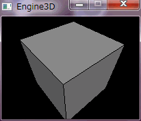
モデルに照明を当て、面法線ベクトルと入射光ベクトルの成す角度に応じて、各面に色を付ける。
カリングで片面のみ表示する事で、描画速度を向上させると共に、不要な面の描画を避ける。 カリングでは、視線ベクトルと面法線ベクトルの成す角度によって表示する面が決まる。 透視投象の前後では頂点座標が異なるため、カリング用と色用とでは、面法線ベクトルを別々に算出しなくてはならない。 照明反射色には、Lambert 照明モデルを使用した。 Lambert は、余弦定理の発見者である。 以下のコードを上のコードに置換、または追加する。 参考資料:DirectX 逆引き大全500の極意(Lambertモデル)
typedef struct{
BYTE r;
BYTE g;
BYTE b;
}COLOR,*LPCOLOR;
typedef struct{
VEC3 v[8]; // 頂点の座標
int f[6][4]; // 各面の頂点番号
VEC3 fn[6]; // 面法線ベクトル
}MODEL,*LPMODEL;
MODEL gmCube; // 立方体情報
float Vec3Dot(VEC3 v1, VEC3 v2);
VEC3 Perspect(VEC3 pos, float look_z);
VEC3 Get_FaceNormal(VEC3 *v);
void M_Create();
void M_Paint(HDC hDC);
// 内積
float Vec3Dot(VEC3 v1, VEC3 v2)
{
return (v1.x * v2.x + v1.y * v2.y + v1.z * v2.z);
}
// 透視投象
VEC3 Perspect(VEC3 pos, float look_z)
{
VEC3 pos_dst;
if(pos.z == look_z){
pos_dst.x = 0;
pos_dst.y = 0;
}
else{
pos_dst.x = pos.x / (pos.z - look_z);
pos_dst.y = pos.y / (pos.z - look_z);
}
pos_dst.z = pos.z;
return pos_dst;
}// Perspect
// 面法線の取得
VEC3 Get_FaceNormal(VEC3 *v)
{
VEC3 v1,v2;
v1 = Vec3Sub(v[2], v[0]);
v2 = Vec3Sub(v[3], v[2]);
return Vec3Normalize(Vec3Cross(v1, v2));
}// Get_FaceNormal
// 初期化
void M_Create()
{
// 立方体作成
Create_Cube();
// 面法線ベクトル算出
int i,j;
VEC3 v[4];
for(i=0; i<6; i++){
for(j=0; j<4; j++){
v[j] = gmCube.v[gmCube.f[i][j]];
}
gmCube.fn[i] = Get_FaceNormal(v);
}
}// M_Create
// 描画
void M_Paint(HDC hDC)
{
int i,j;
VEC3 v_prj[4];
POINT pt[4];
const float d_perspect = HEIGHT; // 透視投象での投影するスクリーンと視点の距離
const POINT offset = {WIDTH / 2, HEIGHT / 2}; // 投象後の二次元座標の平行移動幅
const VEC3 pos_look = {0.0f, 2.0f, -2.0f}; // 視点の位置
const VEC3 pos_lookat = {0, 0, 0}; // 注視点の位置
const VEC3 v_lookup = {0, 1, 0}; // 視点の上向き
VEC3 v_sun = {0.0f,-1.0f,1.0f}; // 入射光のベクトル
VEC3 v_look; // 注視点から視点へのベクトル
HBRUSH hbr,hbrPre;
const float power1 = 0.7f; // 反射の強さ(0 〜 1)
const COLOR material = {255, 255, 255}; // 面のディフューズ色(各色 0 〜 255)
const COLOR ambient = {10, 10, 10}; // 環境光(各色 0 〜 255)
float power2;
UINT r,g,b;
COLOR rgb;
MTRX mt_view,mt_world,mt_worldview;
static int roll_y = 0; // 回転角度
// 行列設定
mt_world = MtrxRotY(roll_y * 3.14f / 180);
mt_view = MtrxView(pos_look, pos_lookat, v_lookup);
mt_worldview = MtrxMult(mt_world, mt_view);
// 入射光ベクトル
v_sun.x = - v_sun.x;
v_sun.y = - v_sun.y;
v_sun.z = - v_sun.z;
v_sun = Vec3Normalize(v_sun);
// 視線ベクトル
v_look = Vec3Normalize(MtrxVec3(Vec3Sub(pos_lookat, pos_look), mt_view));
for(i=0; i<6; i++){
for(j=0; j<4; j++){
int index = gmCube.f[i][j];
// 頂点のワールド・ビュー行列変換
VEC3 v = Vec3Normalize(MtrxVec3(gmCube.v[index], mt_worldview));
// 頂点の透視投象
v_prj[j] = Perspect(v, pos_look.z);
// 頂点の拡大と平行移動
pt[j].x = (long)( v_prj[j].x * d_perspect + offset.x);
pt[j].y = (long)(-v_prj[j].y * d_perspect + offset.y);
}
// 面法線ベクトル計算(カリング用)
VEC3 fn_cull = Get_FaceNormal(v_prj);
// 面法線ベクトルのワールド行列変換(色用)
VEC3 fn_color = Vec3Normalize(MtrxVec3(gmCube.fn[i], mt_world));
// カリング
float dot_cull = Vec3Dot(v_look, fn_cull);
if(dot_cull <= 0){ // 片面表示
// Lambert 照明モデルによる拡散反射色設定
power2 = power1 * Vec3Dot(v_sun, fn_color);
if(power2 < 0){
power2 = 0;
}
r = (UINT)(material.r * power2 + ambient.r);
g = (UINT)(material.g * power2 + ambient.g);
b = (UINT)(material.b * power2 + ambient.b);
if(r > 255) r = 255;
if(g > 255) g = 255;
if(b > 255) b = 255;
rgb.r = (BYTE) r;
rgb.g = (BYTE) g;
rgb.b = (BYTE) b;
hbr = (HBRUSH) CreateSolidBrush(RGB(rgb.r, rgb.g, rgb.b));
hbrPre = (HBRUSH) SelectObject(hDC, hbr);
Polygon(hDC, pt, 4);
SelectObject(hDC, hbrPre);
DeleteObject(hbr);
}
}
// 回転角度増
roll_y += 10;
if(roll_y >= 360)
roll_y = 0;
}// M_Paint
|
|
|
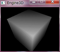
フラットシェーディングは面ごとに色分けしたが、頂点ごとに色分けをして、
各面をそのグラデーションで描画するとグーローシェーディングになる。 グーロー(GOURAUD)は、考案者名である。 グーローシェーディングは、曲面を持つ形状の描画に特に有効である。 頂点色は、頂点法線ベクトルと入射光ベクトルの成す角度によって決まる。 頂点法線ベクトルは、その頂点を含む面の法線ベクトルの和である。 面のグラデーション描画は、GradientFill() で三角形を2つ描画する事で行った。 以下のコードを上のコードに置換、または追加する。 GradientFill() の使用には、msimg32.lib のリンクが必要である。
#pragma comment(lib,"msimg32.lib")
typedef struct{
VEC3 v[8]; // 頂点座標
VEC3 n[8]; // 頂点法線ベクトル
int f[6][4]; // 各面の頂点番号
VEC3 fn[6]; // 面法線ベクトル
}MODEL,*LPMODEL;
void Set_Normal();
void M_Create();
void M_Paint(HDC hDC);
// 面・頂点法線ベクトル算出
void Set_Normal()
{
int i,j,k;
VEC3 n_v,v[4];
// 面法線ベクトル算出
for(i=0; i<6; i++){
for(j=0; j<4; j++){
v[j] = gmCube.v[gmCube.f[i][j]];
}
gmCube.fn[i] = Get_FaceNormal(v);
}
// 頂点法線ベクトル算出
for(i=0; i<8; i++){
n_v.x = 0.0f;
n_v.y = 0.0f;
n_v.z = 0.0f;
for(j=0; j<6; j++){
for(k=0; k<4; k++){
if(i == gmCube.f[j][k]){
n_v.x += gmCube.fn[j].x;
n_v.y += gmCube.fn[j].y;
n_v.z += gmCube.fn[j].z;
break;
}
}
}
gmCube.n[i] = Vec3Normalize(n_v);
}
}// Set_Normal
// 初期化
void M_Create()
{
// 立方体作成
Create_Cube();
// 面・頂点法線ベクトル設定
Set_Normal();
}// M_Create
// 描画
void M_Paint(HDC hDC)
{
int i,j;
VEC3 v_prj[4];
const float d_perspect = HEIGHT; // 透視投象での投影するスクリーンと視点の距離
const POINT offset = {WIDTH / 2, HEIGHT / 2}; // 投象後の二次元座標の平行移動幅
const VEC3 pos_look = {0.0f, 2.0f, -2.0f}; // 視点の位置
const VEC3 pos_lookat = {0, 0, 0}; // 注視点の位置
const VEC3 v_lookup = {0, 1, 0}; // 視点の上向き
VEC3 v_sun = {0.0f, -1.0f, 1.0f}; // 入射光のベクトル
VEC3 v_look; // 注視点から視点へのベクトル
const float power1 = 0.7f; // 反射の強さ(0 〜 1)
const COLOR material = {255, 255, 255}; // 面のディフューズ色(各色 0 〜 255)
const COLOR ambient = {10, 10, 10}; // 環境光(各色 0 〜 255)
float power2;
UINT r,g,b;
COLOR rgb;
MTRX mt_view,mt_world,mt_worldview;
static int roll_y = 0; // 回転角度
TRIVERTEX vert[4];
GRADIENT_TRIANGLE gTri[2];
// 行列設定
mt_world = MtrxRotY(roll_y * 3.14f / 180);
mt_view = MtrxView(pos_look, pos_lookat, v_lookup);
mt_worldview = MtrxMult(mt_world, mt_view);
// 入射光ベクトル
v_sun.x = - v_sun.x;
v_sun.y = - v_sun.y;
v_sun.z = - v_sun.z;
v_sun = Vec3Normalize(v_sun);
// 視線ベクトル
v_look = Vec3Normalize(MtrxVec3(Vec3Sub(pos_lookat, pos_look), mt_view));
for(i=0; i<6; i++){
for(j=0; j<4; j++){
int index = gmCube.f[i][j];
// 頂点のワールド・ビュー行列変換
VEC3 v = Vec3Normalize(MtrxVec3(gmCube.v[index], mt_worldview));
// 頂点の透視投象
v_prj[j] = Perspect(v, pos_look.z);
}
// 面法線ベクトル計算(カリング用)
VEC3 fn_cull = Get_FaceNormal(v_prj);
// カリング
float dot_cull = Vec3Dot(v_look, fn_cull);
if(dot_cull <= 0){ // 片面表示
for(j=0; j<4; j++){
int index = gmCube.f[i][j];
// 頂点法線ベクトルのワールド行列変換
VEC3 n_color = Vec3Normalize(MtrxVec3(gmCube.n[index], mt_world));
// Lambert 照明モデルによる拡散反射色設定
power2 = power1 * Vec3Dot(v_sun, n_color);
if(power2 < 0){
power2 = 0;
}
r = (UINT)(material.r * power2 + ambient.r);
g = (UINT)(material.g * power2 + ambient.g);
b = (UINT)(material.b * power2 + ambient.b);
if(r > 255) r = 255;
if(g > 255) g = 255;
if(b > 255) b = 255;
rgb.r = (BYTE) r;
rgb.g = (BYTE) g;
rgb.b = (BYTE) b;
vert[j].Red = rgb.r << 8;
vert[j].Green = rgb.g << 8;
vert[j].Blue = rgb.b << 8;
vert[j].Alpha = 0x0000;
vert[j].x = (long)( v_prj[j].x * d_perspect + offset.x);
vert[j].y = (long)(-v_prj[j].y * d_perspect + offset.y);
}
gTri[0].Vertex1 = 0;
gTri[0].Vertex2 = 1;
gTri[0].Vertex3 = 2;
gTri[1].Vertex1 = 0;
gTri[1].Vertex2 = 2;
gTri[1].Vertex3 = 3;
GradientFill(hDC, vert, 4, &gTri, 2, GRADIENT_FILL_TRIANGLE);
}
}
// 回転角度増
roll_y += 10;
if(roll_y >= 360)
roll_y = 0;
}// M_Paint
|
|
|
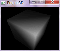
Lambert の代わりに、Phong を使うと、金属的な質感のある立体描写ができる。
Lambert も Phong も考案者名である。 マテリアルやテクスチャが無い場合は、単に置き換えれば良いが、 ある場合は、ポリゴン内の各ピクセル値は以下の式になる。 ピクセル値=テクスチャ色×ディフューズ色×Lambert 照明色+スペキュラ色×Phong 照明色+アンビエント色 この事から、Lambert は陰影に、Phong は光沢のグラデーションに使う事が分かる。 DirectX では、Lambert をディフューズ反射、Phong をスペキュラ反射と呼んでいる。 上のコードの以下の赤字部分を書き換える。 参考資料 Microsoft DirectX9 ヘルプ(簡易 Phong 照明モデル) DirectX 逆引き大全500の極意(金属のような質感 Pシェーダー)
// 描画
void M_Paint(HDC hDC)
{
int i,j;
VEC3 v_prj[4];
const float d_perspect = HEIGHT; // 透視投象での投影するスクリーンと視点の距離
const POINT offset = {WIDTH / 2, HEIGHT / 2}; // 投象後の二次元座標の平行移動幅
const VEC3 pos_look = {0.0f, 2.0f, -2.0f}; // 視点の位置
const VEC3 pos_lookat = {0, 0, 0}; // 注視点の位置
const VEC3 v_lookup = {0, 1, 0}; // 視点の上向き
VEC3 v_sun = {0.0f, -1.0f, 1.0f}; // 入射光のベクトル
VEC3 v_look; // 注視点から視点へのベクトル
const float power1 = 0.7f; // 反射の強さ(0 〜 1)
const int specular_power = 3; // スペキュラ反射の強さ
const COLOR material = {255, 255, 255}; // 面のディフューズ色(各色 0 〜 255)
const COLOR ambient = {10, 10, 10}; // 環境光(各色 0 〜 255)
float power2;
UINT r,g,b;
COLOR rgb;
MTRX mt_view,mt_world,mt_worldview;
static int roll_y = 0; // 回転角度
TRIVERTEX vert[4];
GRADIENT_TRIANGLE gTri[2];
// 行列設定
mt_world = MtrxRotY(roll_y * 3.14f / 180);
mt_view = MtrxView(pos_look, pos_lookat, v_lookup);
mt_worldview = MtrxMult(mt_world, mt_view);
// 入射光ベクトル
v_sun.x = - v_sun.x;
v_sun.y = - v_sun.y;
v_sun.z = - v_sun.z;
v_sun = Vec3Normalize(v_sun);
// 視線ベクトル
v_look = Vec3Normalize(MtrxVec3(Vec3Sub(pos_lookat, pos_look), mt_view));
for(i=0; i<6; i++){
for(j=0; j<4; j++){
int index = gmCube.f[i][j];
// 頂点のワールド・ビュー行列変換
VEC3 v = Vec3Normalize(MtrxVec3(gmCube.v[index], mt_worldview));
// 頂点の透視投象
v_prj[j] = Perspect(v, pos_look.z);
}
// 面法線ベクトル計算(カリング用)
VEC3 fn_cull = Get_FaceNormal(v_prj);
// カリング
float dot_cull = Vec3Dot(v_look, fn_cull);
if(dot_cull <= 0){ // 片面表示
for(j=0; j<4; j++){
int index = gmCube.f[i][j];
// 頂点法線ベクトルのワールド行列変換
VEC3 n_color = Vec3Normalize(MtrxVec3(gmCube.n[index], mt_world));
// 簡易 Phong 照明モデルによるスペキュラ反射色設定
power2 = power1 * (float) pow(Vec3Dot(v_sun, n_color), (int) specular_power);
if(power2 < 0){
power2 = 0;
}
r = (UINT)(material.r * power2 + ambient.r);
g = (UINT)(material.g * power2 + ambient.g);
b = (UINT)(material.b * power2 + ambient.b);
if(r > 255) r = 255;
if(g > 255) g = 255;
if(b > 255) b = 255;
rgb.r = (BYTE) r;
rgb.g = (BYTE) g;
rgb.b = (BYTE) b;
vert[j].Red = rgb.r << 8;
vert[j].Green = rgb.g << 8;
vert[j].Blue = rgb.b << 8;
vert[j].Alpha = 0x0000;
vert[j].x = (long)( v_prj[j].x * d_perspect + offset.x);
vert[j].y = (long)(-v_prj[j].y * d_perspect + offset.y);
}
gTri[0].Vertex1 = 0;
gTri[0].Vertex2 = 1;
gTri[0].Vertex3 = 2;
gTri[1].Vertex1 = 0;
gTri[1].Vertex2 = 2;
gTri[1].Vertex3 = 3;
GradientFill(hDC, vert, 4, &gTri, 2, GRADIENT_FILL_TRIANGLE);
}
}
// 回転角度増
roll_y += 10;
if(roll_y >= 360)
roll_y = 0;
}// M_Paint
|

|
|
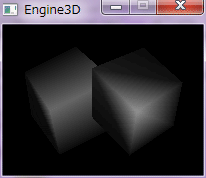
Z バッファ法を使う事で、Z 値に応じたポリゴン描画ができる。
Z バッファ法は、先ず、ウィンドウサイズのZ バッファを作成し、 描画前にZ座標の最奥値で初期化する。 ピクセルを描画する際には、そのピクセルのZ座標とZ バッファの該当座標のZ値と比較し、 小さければ描画し、大きければ描画しない。 描画した後は、Zバッファの該当座標の値をそのピクセルのZ座標で更新する。 Z バッファ法は、凹立体や複数のオブジェクトを描画する際に必要になる。 これを使うには、GradientFill() を自作しなくてはならない。 多角形塗りを利用する。 X,Y座標のクリッピングは、頂点座標が画面内に収まるようにしただけの簡単な手法を用いたが、頂点数が少ないポリゴンでは、正確な描画ができないため、あまり望ましくない。 このビュー・プロジェクション行列では、頂点座標をX軸方向に平行移動すると、カリングが上手くできない。 何か間違えているらしい。カリングを外すと正しく動作する。 以下のコードを上のコードに置換、または追加する。 参考資料: DirectX8.0 3Dアクションゲーム・プログラミング 登大遊著 工学社(Z バッファ法) コンピュータ・グラフィックス J.D.FOLEY/A.VAN DAM著 日本コンピュータ協会 (明度補完)p.594 (多角形のスキャン変換)p.466〜p.470
typedef struct{
BYTE r;
BYTE g;
BYTE b;
}RGBB,*LPRGBB;
typedef struct{
int a;
int r;
int g;
int b;
}ARGBN,*LPARGBN;
typedef struct{
POINT pos; // 頂点座標
ARGBN c; // 頂点照明色
float z; // 頂点Z値
}POLYPAINT,*LPPOLYPAINT;
typedef struct{
int y_min; // 辺の最小Y座標
int y_max; // 辺の最大Y座標
int x_min; // 辺の最小Y座標のX座標
int x; // スキャンラインと辺の交点のX座標
double slant; // 辺の傾きの逆数の整数部
double slant_sum; // slantの和
ARGBN c_min; // 辺の最小Y座標の照明色
ARGBN c_max; // 辺の最大Y座標の照明色
ARGBN color; // 照明色
float z_min; // 辺の最小Y座標のZ値
float z_max; // 辺の最大Y座標のZ値
float z; // Z値
int next; // 次のデータ番号
}EDGE,*LPEDGE;
typedef struct{
int index; // 最初のデータ番号
int last; // 最後のデータ番号
}ET,*LPET;
typedef struct{
float f1;
float f2;
}RATE,*LPRATE;
float gZBuf[HEIGHT][WIDTH]; // Zバッファ
float gZFar = 1; // 再奥Z値
MTRX gMtProj,gMtView,gMtWorld,gMtWorldView,gMtAll;
VEC3 gPosLook,gPosLookAt;
bool gFlagPerspect = false; // false:平行投象、true:射影投象
MTRX MtrxTranslate(float x, float y, float z);
MTRX MtrxScal(float x, float y, float z);
MTRX MtrxPerspect(float zn, float zf, float fov_y, float aspect);
MTRX MtrxOrtho(float zn, float zf, float w, float h);
void Clear_ZBuf();
void Draw_Cube(HDC hDC, VEC3 v_sun);
void Paint_Triangle(HDC hDC, LPPOLYPAINT pp);
void Set_Data1(int idx_min, int idx_max, int &data_ct, LPEDGE data, LPPOLYPAINT pply, LPET et);
void Set_Data2(int idx_min, int idx_max, int &data_ct, LPEDGE data, LPPOLYPAINT pply, LPET et);
void Set_ValRate(LPRATE rate, int idx, int idx_min, int idx_max);
void Set_Color(LPARGBN color, LPRATE rate, ARGBN c_min, ARGBN c_max);
void Set_Z(float *z, LPRATE rate, float z_min, float z_max);
int Round(double val);
void M_Paint(HDC hDC);
// 行列の移動
MTRX MtrxTranslate(float x, float y, float z)
{
MTRX mt = MtrxIdent();
mt._41 = x;
mt._42 = y;
mt._43 = z;
return mt;
}// MtrxTranslate
// 行列のスケーリング
MTRX MtrxScal(float x, float y, float z)
{
MTRX mt = MtrxIdent();
mt._11 = x;
mt._22 = y;
mt._33 = z;
return mt;
}// MtrxScal
// 射影投象行列
MTRX MtrxPerspect(float zn, float zf, float fov_y, float aspect)
{
float c, s, Q;
gFlagPerspect = true;
if(zf == 0){
zf = 0.001f;
}
gZFar = zf;
c = (float) cos(fov_y * 0.5);
s = (float) sin(aspect * 0.5);
if(zn != zf){
Q = s / (1.0f - zn / zf);
}
else{
Q = 1.0f;
}
MTRX mt;
ZeroMemory(&mt, sizeof(mt));
mt._11 = c;
mt._22 = c;
mt._33 = Q;
mt._43 = -Q * zn;
mt._34 = s;
return mt;
}// MtrxPerspect
// 平行投象行列
MTRX MtrxOrtho(float zn, float zf, float w, float h)
{
float sub;
gFlagPerspect = false;
gZFar = zf;
if(zn != zf)
sub = zf - zn;
else
sub = 1;
if(w == 0)
w = 1;
if(h == 0)
h = 1;
MTRX mt;
ZeroMemory(&mt, sizeof(mt));
mt._11 = 2.0f / w;
mt._22 = 2.0f / h;
mt._33 = 1.0f / sub;
mt._43 = - zn / sub;
mt._34 = 1;
return mt;
}// MtrxOrtho
// Zバッファ初期化
void Clear_ZBuf()
{
int i,j;
for(i=0; i<HEIGHT; i++){
for(j=0; j<WIDTH; j++){
gZBuf[i][j] = gZFar;
}
}
}// Clear_ZBuf
// 立方体描画
void Draw_Cube(HDC hDC, VEC3 v_sun)
{
int i,j;
VEC3 v_wv[4],v_all[4];
VEC3 v_look; // 注視点から視点へのベクトル
const int d_perspect = HEIGHT; // 透視投象での投影するスクリーンと視点の距離
const POINT offset = {WIDTH / 2, HEIGHT / 2}; // 投象後の二次元座標の平行移動幅
const float power1 = 0.7f; // 反射の強さ(0 〜 1)
const int specular_power = 3; // スペキュラ反射の強さ
const RGBB material = {255, 255, 255}; // 面のディフューズ色(各色 0 〜 255)
const RGBB ambient = {10, 10, 10}; // 環境光(各色 0 〜 255)
float power2;
UINT r,g,b;
POLYPAINT ply1[4]; // 4頂点ポリゴン色塗り情報
POLYPAINT ply2[2][3]; // 3頂点ポリゴン色塗り情報
gMtWorldView = MtrxMult(gMtWorld, gMtView);
gMtAll = MtrxMult(gMtWorldView, gMtProj);
// 視線ベクトル
VEC3 posLookAt = MtrxVec3(gPosLookAt, gMtWorld);
v_look = Vec3Normalize(MtrxVec3(Vec3Sub(posLookAt, gPosLook), gMtView));
for(i=0; i<6; i++){
for(j=0; j<4; j++){
int index = gmCube.f[i][j];
// 頂点のワールド・ビュー行列変換
v_wv[j] = Vec3Normalize(MtrxVec3(gmCube.v[index], gMtWorldView));
}
// 面法線ベクトル計算(カリング用)
VEC3 fn_cull = Get_FaceNormal(v_wv);
// カリング
float dot_cull = Vec3Dot(v_look, fn_cull);
if(dot_cull < 0){ // 片面表示
for(j=0; j<4; j++){
int index = gmCube.f[i][j];
// 頂点のワールド・ビュー・プロジェクション行列変換
v_all[j] = MtrxVec3(gmCube.v[index], gMtAll);
// 頂点法線ベクトルのワールド行列変換
VEC3 n_color;
n_color = MtrxVec3(gmCube.n[index], gMtWorld);
n_color = Vec3Normalize(n_color);
// 簡易 Phong 照明モデルによるスペキュラ反射色設定
power2 = power1 * (float) pow(Vec3Dot(v_sun, n_color), (int) specular_power);
if(power2 < 0){
power2 = 0;
}
r = (UINT)(material.r * power2 + ambient.r);
g = (UINT)(material.g * power2 + ambient.g);
b = (UINT)(material.b * power2 + ambient.b);
if(r > 255) r = 255;
if(g > 255) g = 255;
if(b > 255) b = 255;
float size_rate = d_perspect;
if(gFlagPerspect)
size_rate /= (v_all[j].z + gPosLookAt.z - gPosLook.z);
ply1[j].pos.x = (long)( v_all[j].x * size_rate + offset.x);
ply1[j].pos.y = (long)(-v_all[j].y * size_rate + offset.y);
ply1[j].z = v_all[j].z;
ply1[j].c.a = 0;
ply1[j].c.r = r;
ply1[j].c.g = g;
ply1[j].c.b = b;
}
ply2[0][0] = ply1[0];
ply2[0][1] = ply1[1];
ply2[0][2] = ply1[2];
ply2[1][0] = ply1[0];
ply2[1][1] = ply1[2];
ply2[1][2] = ply1[3];
Paint_Triangle(hDC, ply2[0]);
Paint_Triangle(hDC, ply2[1]);
}
}
}// Draw_Cube
// 三角形塗り
// pply : 三角形の頂点と色のリスト
void Paint_Triangle(HDC hDC, LPPOLYPAINT pply)
{
EDGE data[3]; // 頂点リスト
EDGE aet[2]; // アクティブ辺テーブル(AET)
ET et[HEIGHT]; // 辺テーブル(ET)
int i,j,y_min,y_max,prev,next,next2,data_ct,aet_ct,y_next;
float z = 0; // Z 値
ARGBN argbLight;
RATE rate;
// Y座標のクリッピング
for(i=0; i<3; i++){
if(pply[i].pos.y < 0)
pply[i].pos.y = 0;
if(pply[i].pos.y >= HEIGHT)
pply[i].pos.y = HEIGHT - 1;
}
// Y座標の最大値と最小値を求める
y_min = pply[0].pos.y;
y_max = pply[0].pos.y;
for(i=1; i<3; i++){
if(pply[i].pos.y < y_min){
y_min = pply[i].pos.y;
}
else if(pply[i].pos.y > y_max)
y_max = pply[i].pos.y;
}
// 頂点リスト初期化
for(i=0; i<3; i++){
data[i].next = -1;
}
// ET 初期化
for(i=y_min; i<=y_max; i++){
et[i].index = -1;
et[i].last = -1;
}
data_ct = 0; // data の要素数
for(i=0; i<3; i++){
prev = i - 1;
if(prev < 0){
prev = 2;
}
next = i + 1;
if(next >= 3){
next = 0;
}
if(pply[i].pos.y < pply[prev].pos.y && pply[i].pos.y < pply[next].pos.y){
Set_Data1(i, prev, data_ct, data, pply, et);
Set_Data1(i, next, data_ct, data, pply, et);
}
else if(pply[i].pos.y > pply[prev].pos.y && pply[i].pos.y < pply[next].pos.y){
Set_Data2(i, next, data_ct, data, pply, et);
}
else if(pply[i].pos.y > pply[next].pos.y && pply[i].pos.y < pply[prev].pos.y){
Set_Data2(i, prev, data_ct, data, pply, et);
}
else if(pply[i].pos.y == pply[prev].pos.y && pply[i].pos.y < pply[next].pos.y){
Set_Data1(i, next, data_ct, data, pply, et);
}
else if(pply[i].pos.y == pply[next].pos.y && pply[i].pos.y < pply[prev].pos.y){
Set_Data1(i, prev, data_ct, data, pply, et);
}
else if(pply[i].pos.y == pply[next].pos.y && pply[i].pos.y == pply[prev].pos.y){
Set_Data1(i, i, data_ct, data, pply, et);
}
}
// スキャン・ライン・アルゴリズムによる塗り潰し
aet_ct = 0; // AET の要素数
for(i=y_min; i<=y_max; i++){
// スキャンライン上の頂点を検索
if(et[i].index != -1){
aet[aet_ct ++] = data[et[i].index];
next2 = data[et[i].index].next;
if(next2 != -1){
aet[aet_ct ++] = data[next2];
next2 = data[next2].next;
}
}
// AET を x について昇順にソート
if(aet[0].x > aet[1].x){
EDGE e = aet[0];
aet[0] = aet[1];
aet[1] = e;
}
// X座標のクリッピング
if(aet[0].x < 0){
aet[0].x = 0;
}
if(aet[1].x >= WIDTH){
aet[1].x = WIDTH - 1;
}
// スキャンラインの描画
for(j=aet[0].x;j<aet[1].x;j++){
Set_ValRate(&rate, j, aet[0].x, aet[1].x);
Set_Z(&z, &rate, aet[0].z, aet[1].z);
if(z < gZBuf[i][j]){ // ピクセルごとの Z バッファ判定
gZBuf[i][j] = z;
// 照明色
Set_Color(&argbLight, &rate, aet[0].color, aet[1].color);
BYTE r = (BYTE) argbLight.r;
BYTE g = (BYTE) argbLight.g;
BYTE b = (BYTE) argbLight.b;
// ピクセル値設定
SetPixel(hDC, j ,i, RGB(r,g,b));
}
}
// i == y_max の要素を AET から削除
if(i == aet[1].y_max){
aet_ct --;
}
if(i == aet[0].y_max){
aet[0] = aet[1];
aet_ct --;
}
// AET の各 x を次のスキャンラインでの値に更新
for(j=0;j<2;j++){
y_next = i + 1;
aet[j].x = Round(aet[j].x_min + aet[j].slant_sum);
aet[j].slant_sum += aet[j].slant;
Set_ValRate(&rate, y_next, aet[j].y_min, aet[j].y_max);
Set_Color(&aet[j].color, &rate, aet[j].c_min, aet[j].c_max);
Set_Z(&aet[j].z, &rate, aet[j].z_min, aet[j].z_max);
}
}
}// Paint_Triangle
// 頂点リスト設定1
void Set_Data1(int idx_min, int idx_max, int &data_ct, LPEDGE data, LPPOLYPAINT pply, LPET et)
{
int et_idx = pply[idx_min].pos.y;
if(et[et_idx].last == -1)
et[et_idx].index = data_ct;
else
data[et[et_idx].last].next = data_ct;
et[et_idx].last = data_ct;
data[data_ct].y_min = pply[idx_min].pos.y;
data[data_ct].y_max = pply[idx_max].pos.y;
data[data_ct].x_min = pply[idx_min].pos.x;
data[data_ct].x = data[data_ct].x_min;
data[data_ct].slant = (double)(pply[idx_max].pos.x - pply[idx_min].pos.x) / (pply[idx_max].pos.y - pply[idx_min].pos.y);
data[data_ct].slant_sum = data[data_ct].slant;
data[data_ct].c_min = pply[idx_min].c;
data[data_ct].c_max = pply[idx_max].c;
data[data_ct].color = data[data_ct].c_min;
data[data_ct].z_min = pply[idx_min].z;
data[data_ct].z_max = pply[idx_max].z;
data[data_ct].z = data[data_ct].z_min;
data_ct ++;
}// Set_Data1
// 頂点リスト設定2
void Set_Data2(int idx_min, int idx_max, int &data_ct, LPEDGE data, LPPOLYPAINT pply, LPET et)
{
int et_idx = pply[idx_min].pos.y + 1;
if(et[et_idx].last == -1)
et[et_idx].index = data_ct;
else
data[et[et_idx].last].next = data_ct;
et[et_idx].last = data_ct;
double slant = (double)(pply[idx_max].pos.x - pply[idx_min].pos.x) / (pply[idx_max].pos.y - pply[idx_min].pos.y);
RATE rate;
float z;
ARGBN color;
Set_ValRate(&rate, et_idx, pply[idx_min].pos.y, pply[idx_max].pos.y);
data[data_ct].y_min = pply[idx_min].pos.y;
data[data_ct].y_max = pply[idx_max].pos.y;
data[data_ct].x_min = pply[idx_min].pos.x;
data[data_ct].x = Round(data[data_ct].x_min + slant);
data[data_ct].slant = slant;
data[data_ct].slant_sum = data[data_ct].slant + slant;
Set_Color(&color, &rate, pply[idx_min].c, pply[idx_max].c);
data[data_ct].c_min = pply[idx_min].c;
data[data_ct].c_max = pply[idx_max].c;
data[data_ct].color = color;
Set_Z(&z, &rate, pply[idx_min].z, pply[idx_max].z);
data[data_ct].z_min = pply[idx_min].z;
data[data_ct].z_max = pply[idx_max].z;
data[data_ct].z = z;
data_ct ++;
}// Set_Data2
// 比率設定
void Set_ValRate(LPRATE rate, int idx, int idx_min, int idx_max)
{
if(idx_min != idx_max){
rate->f1 = (float)(idx - idx_min) / (idx_max - idx_min);
rate->f2 = 1 - rate->f1;
}
else{
rate->f1 = -1;
}
}// Set_ValRate
// 色設定
void Set_Color(LPARGBN color, LPRATE rate, ARGBN c_min, ARGBN c_max)
{
if(rate->f1 != -1){
color->a = (BYTE)(c_max.a * rate->f1 + c_min.a * rate->f2);
color->r = (BYTE)(c_max.r * rate->f1 + c_min.r * rate->f2);
color->g = (BYTE)(c_max.g * rate->f1 + c_min.g * rate->f2);
color->b = (BYTE)(c_max.b * rate->f1 + c_min.b * rate->f2);
}
else{
*color = c_min;
}
}// Set_Color
// Z値設定
void Set_Z(float *z, LPRATE rate, float z_min, float z_max)
{
if(rate->f1 != -1){
*z = z_max * rate->f1 + z_min * rate->f2;
}
else{
*z = z_min;
}
}// Set_Z
// 浮動小数点数を四捨五入して整数にする
int Round(double val)
{
return (int)(val + 0.5f);
}// Round
// 描画
void M_Paint(HDC hDC)
{
const VEC3 pos_look = {0.0f, 2.0f, -2.0f}; // 視点の位置
const VEC3 pos_lookat = {0.0f, 0.0f, 0.0f}; // 注視点の位置
const VEC3 v_lookup = {0, 1, 0}; // 視点の上向き
VEC3 v_sun = {0.0f, -1.0f, 1.0f}; // 入射光のベクトル
const RGBB material = {255, 255, 255}; // 面のディフューズ色(各色 0 〜 255)
const RGBB ambient = {10, 10, 10}; // 環境光(各色 0 〜 255)
MTRX mtScal,mtRotY,mtTrans,mtWork;
static int roll_y = 0; // 回転角度
// 行列設定
gMtView = MtrxView(pos_look, pos_lookat, v_lookup);
gMtProj = MtrxPerspect(0.0f, 10.0f, 3.14f / 4, 1.0f);
// gMtProj = MtrxOrtho(0.0f, 10.0f, 5.0f, 5.0f);
// 入射光ベクトル
v_sun.x = - v_sun.x;
v_sun.y = - v_sun.y;
v_sun.z = - v_sun.z;
v_sun = Vec3Normalize(v_sun);
// Zバッファ初期化
Clear_ZBuf();
// オブジェクト描画
mtScal = MtrxScal(1.0f, 1.0f, 1.0f);
mtRotY = MtrxRotY(roll_y * 3.14f / 180);
mtTrans = MtrxTranslate(-0.4f, 0.2f, 0.0f);
mtWork = MtrxMult(mtScal, mtRotY);
gMtWorld = MtrxMult(mtWork, mtTrans);
Draw_Cube(hDC, v_sun);
mtTrans = MtrxTranslate(0.4f, 0.0f, 0.2f);
gMtWorld = MtrxMult(mtWork, mtTrans);
Draw_Cube(hDC, v_sun);
// 回転角度増
roll_y += 10;
if(roll_y >= 360)
roll_y = 0;
}// M_Paint
|
|
|
ステンシル バッファは、1度書き込んだピクセルには、書き込めないようにする手法である。
その仕組みは、Z バッファ法と、ほぼ同様である。 上のコードに以下の赤字部分を追加する。 参考資料:0からのゲームプログラミング (http://www.plustarnet.com/aspil/Programming/)影 2 bool gStencilBuf[HEIGHT][WIDTH]; // ステンシル バッファ bool gFlagStencilWrite = false; // ステンシル バッファ有効化フラグ(書き込み用) bool gFlagStencilJudge = false; // ステンシル バッファ有効化フラグ(判定用) void Clear_Z_StencilBuf(); void Paint_Triangle(HDC hDC, LPPOLYPAINT pp); void M_Paint(HDC hDC); // Z・ステンシルバッファ初期化 void Clear_Z_StencilBuf() { int i,j; for(i=0; i<HEIGHT; i++){ for(j=0; j<WIDTH; j++){ gZBuf[i][j] = gZFar; gStencilBuf[i][j] = false; } } }// Clear_Z_StencilBuf // 三角形塗り // pply : 三角形の頂点と色のリスト void Paint_Triangle(HDC hDC, LPPOLYPAINT pply) { EDGE data[3]; // 頂点リスト EDGE aet[2]; // アクティブ辺テーブル(AET) ET et[HEIGHT]; // 辺テーブル(ET) int i,j,y_min,y_max,prev,next,next2,data_ct,aet_ct,y_next; float z = 0; // Z 値 ARGBN argbLight; RATE rate; // Y座標のクリッピング for(i=0; i<3; i++){ if(pply[i].pos.y < 0) pply[i].pos.y = 0; if(pply[i].pos.y >= HEIGHT) pply[i].pos.y = HEIGHT - 1; } // Y座標の最大値と最小値を求める y_min = pply[0].pos.y; y_max = pply[0].pos.y; for(i=1; i<3; i++){ if(pply[i].pos.y < y_min){ y_min = pply[i].pos.y; } else if(pply[i].pos.y > y_max) y_max = pply[i].pos.y; } // 頂点リスト初期化 for(i=0; i<3; i++){ data[i].next = -1; } // ET 初期化 for(i=y_min; i<=y_max; i++){ et[i].index = -1; et[i].last = -1; } data_ct = 0; // data の要素数 for(i=0; i<3; i++){ prev = i - 1; if(prev < 0){ prev = 2; } next = i + 1; if(next >= 3){ next = 0; } if(pply[i].pos.y < pply[prev].pos.y && pply[i].pos.y < pply[next].pos.y){ Set_Data1(i, prev, data_ct, data, pply, et); Set_Data1(i, next, data_ct, data, pply, et); } else if(pply[i].pos.y > pply[prev].pos.y && pply[i].pos.y < pply[next].pos.y){ Set_Data2(i, next, data_ct, data, pply, et); } else if(pply[i].pos.y > pply[next].pos.y && pply[i].pos.y < pply[prev].pos.y){ Set_Data2(i, prev, data_ct, data, pply, et); } else if(pply[i].pos.y == pply[prev].pos.y && pply[i].pos.y < pply[next].pos.y){ Set_Data1(i, next, data_ct, data, pply, et); } else if(pply[i].pos.y == pply[next].pos.y && pply[i].pos.y < pply[prev].pos.y){ Set_Data1(i, prev, data_ct, data, pply, et); } else if(pply[i].pos.y == pply[next].pos.y && pply[i].pos.y == pply[prev].pos.y){ Set_Data1(i, i, data_ct, data, pply, et); } } // スキャン・ライン・アルゴリズムによる塗り潰し aet_ct = 0; // AET の要素数 for(i=y_min; i<=y_max; i++){ // スキャンライン上の頂点を検索 if(et[i].index != -1){ aet[aet_ct ++] = data[et[i].index]; next2 = data[et[i].index].next; if(next2 != -1){ aet[aet_ct ++] = data[next2]; next2 = data[next2].next; } } // AET を x について昇順にソート if(aet[0].x > aet[1].x){ EDGE e = aet[0]; aet[0] = aet[1]; aet[1] = e; } // X座標のクリッピング if(aet[0].x < 0){ aet[0].x = 0; } if(aet[1].x >= WIDTH){ aet[1].x = WIDTH - 1; } // スキャンラインの描画 for(j=aet[0].x;j<aet[1].x;j++){ Set_ValRate(&rate, j, aet[0].x, aet[1].x); Set_Z(&z, &rate, aet[0].z, aet[1].z); if(z < gZBuf[i][j] && (!gFlagStencilJudge || gFlagStencilJudge && !gStencilBuf[i][j])) // ピクセルごとの Z バッファ・ステンシル バッファ判定 { gZBuf[i][j] = z; if(gFlagStencilWrite){ gStencilBuf[i][j] = true; } // 照明色 Set_Color(&argbLight, &rate, aet[0].color, aet[1].color); BYTE r = (BYTE) argbLight.r; BYTE g = (BYTE) argbLight.g; BYTE b = (BYTE) argbLight.b; // ピクセル値設定 SetPixel(hDC, j ,i, RGB(r,g,b)); } } // i == y_max の要素を AET から削除 if(i == aet[1].y_max){ aet_ct --; } if(i == aet[0].y_max){ aet[0] = aet[1]; aet_ct --; } // AET の各 x を次のスキャンラインでの値に更新 for(j=0;j<2;j++){ y_next = i + 1; aet[j].x = Round(aet[j].x_min + aet[j].slant_sum); aet[j].slant_sum += aet[j].slant; Set_ValRate(&rate, y_next, aet[j].y_min, aet[j].y_max); Set_Color(&aet[j].color, &rate, aet[j].c_min, aet[j].c_max); Set_Z(&aet[j].z, &rate, aet[j].z_min, aet[j].z_max); } } }// Paint_Triangle // 描画 void M_Paint(HDC hDC) { const VEC3 pos_look = {0.0f, 2.0f, -2.0f}; // 視点の位置 const VEC3 pos_lookat = {0.0f, 0.0f, 0.0f}; // 注視点の位置 const VEC3 v_lookup = {0, 1, 0}; // 視点の上向き VEC3 v_sun = {0.0f, -1.0f, 1.0f}; // 入射光のベクトル const RGBB material = {255, 255, 255}; // 面のディフューズ色(各色 0 〜 255) const RGBB ambient = {10, 10, 10}; // 環境光(各色 0 〜 255) MTRX mtScal,mtRotY,mtTrans,mtWork; static int roll_y = 0; // 回転角度 // 行列設定 gMtView = MtrxView(pos_look, pos_lookat, v_lookup); gMtProj = MtrxPerspect(0.0f, 10.0f, 3.14f / 4, 1.0f); // gMtProj = MtrxOrtho(0.0f, 10.0f, 5.0f, 5.0f); // 入射光ベクトル v_sun.x = - v_sun.x; v_sun.y = - v_sun.y; v_sun.z = - v_sun.z; v_sun = Vec3Normalize(v_sun); // Z・ステンシルバッファ初期化 Clear_Z_StencilBuf(); // オブジェクト描画 mtScal = MtrxScal(1.0f, 1.0f, 1.0f); mtRotY = MtrxRotY(roll_y * 3.14f / 180); mtTrans = MtrxTranslate(-0.4f, 0.2f, 0.0f); mtWork = MtrxMult(mtScal, mtRotY); gMtWorld = MtrxMult(mtWork, mtTrans); gFlagStencilWrite = true; gFlagStencilJudge = false; Draw_Cube(hDC, v_sun); mtTrans = MtrxTranslate(0.4f, 0.0f, 0.2f); gMtWorld = MtrxMult(mtWork, mtTrans); gFlagStencilWrite = false; gFlagStencilJudge = true; Draw_Cube(hDC, v_sun); // 回転角度増 roll_y += 10; if(roll_y >= 360) roll_y = 0; }// M_Paint |
|
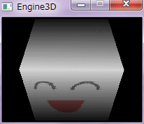
SetPixel() は、実は描画が遅く、ピクセル値を直接操作した方が速い。
また、
for(j=0; j<hgt; j++){
    for(i=0; i<wdh; i++){
        pbits[j * stride + i * 3 + 0] = b;
        pbits[j * stride + i * 3 + 1] = g;
        pbits[j * stride + i * 3 + 2] = r;
    }
}
とするよりも、
int stride_sum = 0;
for(j=0; j<hgt; j++){
    BYTE pb = pbits + stride_sum;
    for(i=0; i<wdh; i++){
        *pb ++ = b;
        *pb ++ = g;
        *pb ++ = r;
    }
    stride_sum += stride;
}
とした方が描画が速くなる。乗除よりも加減やシフトの方が演算速度が速いからである。 もう1つの掛け算速度を上げる方法が、テーブル演算である。 例えば、3 * 5 = 15 という計算をする時、予め、table[3][5] = 15 という計算結果を入れた配列を用意しておけば、計算速度の向上が見込める。 例えば、半透明描画は、 BYTE r1 = 255,g1 = 32,b1 = 32,r2 = 0,g2 = 0,b2 = 255; float alpha1 = 0.5f; float alpha2 = 1.0f - alpha1; BYTE r = (BYTE)(r1 * alpha1 + r2 * alpha2); BYTE g = (BYTE)(g1 * alpha1 + g2 * alpha2); BYTE b = (BYTE)(b1 * alpha1 + b2 * alpha2);で計算されるが、予め
BYTE table[256][256];
for(i=0; i<256; i++){
    for(j=0; j<256; j++){
        table[i][j] = i * j / 255;
    }
}
という掛け算テーブルを作っておけば、
BYTE alpha1 = (BYTE)(0.5f * 255);
BYTE alpha2 = 255 - alpha1;
BYTE r = table[r1][alpha1] + table[r2][alpha2];
BYTE g = table[g1][alpha1] + table[g2][alpha2];
BYTE b = table[b1][alpha1] + table[b2][alpha2];
とできるから、掛け算をしなくて済むというわけである。 Z バッファ法のコードに以下の赤字部分を追加する。 参考資料:DirectX Programmers Page (http://www.interq.or.jp/black/minami-m/) GDI 描画ライブラリ #define COLOR_BYTE COLOR_BIT / 8 // 作業用DIBの色深度(バイト) #define MULT1 255 // 掛け算対応表の被乗数の最大値 #define MULT2 255 // 掛け算対応表の乗数の最大値 typedef struct{ float f1; float f2; int n1; int n2; }RATE,*LPRATE; UINT gnStride = 0; // 作業用DIBの4バイト境界幅 BYTE gMultTbl[MULT1+1][MULT2+1]; // 掛け算の対応表(比率) D3DXMATRIX gMtProj,gMtView,gMtWorld,gMtWorldView,gMtAll; void Create_Work_Dib(); void Paint_Triangle(HDC hDC, LPPOLYPAINT pp); void Set_ValRate(LPRATE rate, int idx, int idx_min, int idx_max); void Set_Color(LPARGBN color, LPRATE rate, ARGBN c_min, ARGBN c_max); void M_Create(); void M_Paint(HDC hDC); // 作業用DIBの作成 void Create_Work_Dib() { BITMAPINFO bmi; ZeroMemory(&bmi, sizeof(bmi)); bmi.bmiHeader.biSize = sizeof(BITMAPINFOHEADER); bmi.bmiHeader.biWidth = WIDTH; bmi.bmiHeader.biHeight = -HEIGHT; bmi.bmiHeader.biPlanes = 1; bmi.bmiHeader.biBitCount = COLOR_BIT; bmi.bmiHeader.biCompression = BI_RGB; ghBmpWork = (HBITMAP) CreateDIBSection(NULL, &bmi, DIB_RGB_COLORS, (VOID **)&gpBitsWork, NULL, 0); gnStride = WIDTHBYTES(WIDTH * COLOR_BIT); int workSize = gnStride * HEIGHT; ZeroMemory(gpBitsWork, workSize); }// Create_Work_Dib // 三角形塗り // pply : 三角形の頂点と色のリスト void Paint_Triangle(HDC hDC, LPPOLYPAINT pply) { EDGE data[3]; // 頂点リスト EDGE aet[2]; // アクティブ辺テーブル(AET) ET et[HEIGHT]; // 辺テーブル(ET) int i,j,y_min,y_max,prev,next,next2,data_ct,aet_ct,y_next; UINT stride_sum; float z = 0; // Z 値 ARGBN argbLight; RATE rate; // Y座標のクリッピング for(i=0; i<3; i++){ if(pply[i].pos.y < 0) pply[i].pos.y = 0; if(pply[i].pos.y >= HEIGHT) pply[i].pos.y = HEIGHT - 1; } // Y座標の最大値と最小値を求める y_min = pply[0].pos.y; y_max = pply[0].pos.y; for(i=1; i<3; i++){ if(pply[i].pos.y < y_min){ y_min = pply[i].pos.y; } else if(pply[i].pos.y > y_max) y_max = pply[i].pos.y; } // 頂点リスト初期化 for(i=0; i<3; i++){ data[i].next = -1; } // ET 初期化 for(i=y_min; i<=y_max; i++){ et[i].index = -1; et[i].last = -1; } data_ct = 0; // data の要素数 for(i=0; i<3; i++){ prev = i - 1; if(prev < 0){ prev = 2; } next = i + 1; if(next >= 3){ next = 0; } if(pply[i].pos.y < pply[prev].pos.y && pply[i].pos.y < pply[next].pos.y){ Set_Data1(i, prev, data_ct, data, pply, et); Set_Data1(i, next, data_ct, data, pply, et); } else if(pply[i].pos.y > pply[prev].pos.y && pply[i].pos.y < pply[next].pos.y){ Set_Data2(i, next, data_ct, data, pply, et); } else if(pply[i].pos.y > pply[next].pos.y && pply[i].pos.y < pply[prev].pos.y){ Set_Data2(i, prev, data_ct, data, pply, et); } else if(pply[i].pos.y == pply[prev].pos.y && pply[i].pos.y < pply[next].pos.y){ Set_Data1(i, next, data_ct, data, pply, et); } else if(pply[i].pos.y == pply[next].pos.y && pply[i].pos.y < pply[prev].pos.y){ Set_Data1(i, prev, data_ct, data, pply, et); } else if(pply[i].pos.y == pply[next].pos.y && pply[i].pos.y == pply[prev].pos.y){ Set_Data1(i, i, data_ct, data, pply, et); } } // スキャン・ライン・アルゴリズムによる塗り潰し aet_ct = 0; // AET の要素数 stride_sum = y_min * gnStride; for(i=y_min; i<=y_max; i++){ // スキャンライン上の頂点を検索 if(et[i].index != -1){ aet[aet_ct ++] = data[et[i].index]; next2 = data[et[i].index].next; if(next2 != -1){ aet[aet_ct ++] = data[next2]; next2 = data[next2].next; } } // AET を x について昇順にソート if(aet[0].x > aet[1].x){ EDGE e = aet[0]; aet[0] = aet[1]; aet[1] = e; } // X座標のクリッピング if(aet[0].x < 0){ aet[0].x = 0; } if(aet[1].x >= WIDTH){ aet[1].x = WIDTH - 1; } // スキャンラインの描画 LPBYTE pb = gpBitsWork + stride_sum + aet[0].x * COLOR_BYTE; for(j=aet[0].x;j<aet[1].x;j++){ Set_ValRate(&rate, j, aet[0].x, aet[1].x); Set_Z(&z, &rate, aet[0].z, aet[1].z); if(z < gZBuf[i][j]){ // ピクセルごとの Z バッファ判定 gZBuf[i][j] = z; // 照明色 Set_Color(&argbLight, &rate, aet[0].color, aet[1].color); BYTE r = (BYTE) argbLight.r; BYTE g = (BYTE) argbLight.g; BYTE b = (BYTE) argbLight.b; // ピクセル値設定 *pb ++ = b; *pb ++ = g; *pb ++ = r; } else{ pb += COLOR_BYTE; } } stride_sum += gnStride; // i == y_max の要素を AET から削除 if(i == aet[1].y_max){ aet_ct --; } if(i == aet[0].y_max){ aet[0] = aet[1]; aet_ct --; } // AET の各 x を次のスキャンラインでの値に更新 for(j=0;j<2;j++){ y_next = i + 1; aet[j].x = Round(aet[j].x_min + aet[j].slant_sum); aet[j].slant_sum += aet[j].slant; Set_ValRate(&rate, y_next, aet[j].y_min, aet[j].y_max); Set_Color(&aet[j].color, &rate, aet[j].c_min, aet[j].c_max); Set_Z(&aet[j].z, &rate, aet[j].z_min, aet[j].z_max); } } }// Paint_Triangle // 比率設定 void Set_ValRate(LPRATE rate, int idx, int idx_min, int idx_max) { if(idx_min != idx_max){ rate->f1 = (float)(idx - idx_min) / (idx_max - idx_min); rate->f2 = 1 - rate->f1; rate->n1 = (int)(rate->f1 * MULT2); rate->n2 = MULT2 - rate->n1; } else{ rate->f1 = -1; rate->n1 = -1; } }// Set_ValRate // 色設定 void Set_Color(LPARGBN color, LPRATE rate, ARGBN c_min, ARGBN c_max) { if(rate->n1 != -1){ color->a = gMultTbl[c_max.a][rate->n1] + gMultTbl[c_min.a][rate->n2]; color->r = gMultTbl[c_max.r][rate->n1] + gMultTbl[c_min.r][rate->n2]; color->g = gMultTbl[c_max.g][rate->n1] + gMultTbl[c_min.g][rate->n2]; color->b = gMultTbl[c_max.b][rate->n1] + gMultTbl[c_min.b][rate->n2]; } else{ *color = c_min; } }// Set_Color // 初期化 void M_Create() { // 立方体作成 Create_Cube(); // 面・頂点法線ベクトル設定 Set_Normal(); // 掛け算対応表作成 int i,j; for(i=0; i<=MULT1; i++){ for(j=0; j<=MULT2; j++){ gMultTbl[i][j] = ((i * j) / MULT2); } } }// M_Create |
|
|
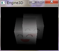
テクスチャ座標の取り扱いは、基本的に照明色やZ値と同じ。
上のコードに以下の赤字部分を置換または追加する。
typedef struct{
float x;
float y;
}VEC2,*LPVEC2;
typedef struct{
POINT pos; // 頂点座標
ARGBN c1; // 頂点ディフューズ色
ARGBN c2; // 頂点スペキュラ色
float z; // 頂点Z値
VEC2 t; // テクスチャ座標
}POLYPAINT,*LPPOLYPAINT;
typedef struct{
int y_min; // 辺の最小Y座標
int y_max; // 辺の最大Y座標
int x_min; // 辺の最小Y座標のX座標
int x; // スキャンラインと辺の交点のX座標
double slant; // 辺の傾きの逆数の整数部
double slant_sum; // slantの和
ARGBN c1_min; // 辺の最小Y座標のディフューズ色
ARGBN c1_max; // 辺の最大Y座標のディフューズ色
ARGBN color1; // ディフューズ色
ARGBN c2_min; // 辺の最小Y座標のスペキュラ色
ARGBN c2_max; // 辺の最大Y座標のスペキュラ色
ARGBN color2; // スペキュラ色
float z_min; // 辺の最小Y座標のZ値
float z_max; // 辺の最大Y座標のZ値
float z; // Z値
VEC2 t_min; // 辺の最小Y座標のテクスチャ座標
VEC2 t_max; // 辺の最大Y座標のテクスチャ座標
VEC2 texcrd; // テクスチャ座標
int next; // 次のデータ番号
}EDGE,*LPEDGE;
typedef struct{
VEC3 v[8]; // 頂点座標
VEC3 n[8]; // 頂点法線ベクトル
VEC2 t[8]; // テクスチャ座標
int f[6][4]; // 各面の頂点番号
VEC3 fn[6]; // 面法線ベクトル
}MODEL,*LPMODEL;
typedef struct{
HBITMAP hBmp;
UINT width,height,stride;
LPDWORD pBits;
}TEX,*LPTEX;
TEX gTex; // テクスチャ情報
const RGBB gAmbient = {10, 10, 10}; // 環境光(各色 0 〜 255)
const int gSpecularPower = 3; // スペキュラ反射の強さ
void Create_Cube();
void Draw_Cube(HDC hDC, VEC3 v_sun);
void Paint_Triangle(HDC hDC, LPPOLYPAINT pp);
void Set_Data1(int idx_min, int idx_max, int &data_ct, LPEDGE data, LPPOLYPAINT pply, LPET et);
void Set_Data2(int idx_min, int idx_max, int &data_ct, LPEDGE data, LPPOLYPAINT pply, LPET et);
void Set_TexCrd(VEC2 *texcrd, LPRATE rate, VEC2 t_min, VEC2 t_max);
void M_Create();
void M_Paint(HDC hDC);
void M_Close();
// 立方体の作成
void Create_Cube()
{
VEC3 v[8] = {{0.5f,0.5f,-0.5f},{0.5f,0.5f,0.5f},{-0.5f,0.5f,0.5f},
{-0.5f,0.5f,-0.5f},{0.5f,-0.5f,-0.5f},{0.5f,-0.5f,0.5f},
{-0.5f,-0.5f,0.5f},{-0.5f,-0.5f,-0.5f}};
VEC2 t[8] = {{0,0},{0,0},{1,0},{1,0},{0,1},{0,1},{1,1},{1,1}};
int f[6][4] = {{3,2,1,0},{0,1,5,4},{1,2,6,5},{2,3,7,6},{3,0,4,7},{4,5,6,7}};
memcpy(gmCube.v, v, sizeof(gmCube.v));
memcpy(gmCube.t, t, sizeof(gmCube.t));
memcpy(gmCube.f, f, sizeof(gmCube.f));
}// Create_Cube
// 立方体描画
void Draw_Cube(HDC hDC, VEC3 v_sun)
{
int i,j;
VEC3 v_wv[4],v_all[4];
const float d_perspect = HEIGHT; // 透視投象での投影するスクリーンと視点の距離
const POINT offset = {WIDTH / 2, HEIGHT / 2}; // 投象後の二次元座標の平行移動幅
const float power1 = 0.7f; // 反射の強さ(0 〜 1)
const RGBB diffuse = {255, 255, 255}; // 面のディフューズ色(各色 0 〜 255)
const RGBB specular = {255, 255, 255}; // 面のスペキュラ色(各色 0 〜 255)
float power2,powerDiffuse,powerSpecular;
ARGBN argbDiffuse,argbSpecular;
POLYPAINT ply1[4]; // 4頂点ポリゴン色塗り情報
POLYPAINT ply2[2][3]; // 3頂点ポリゴン色塗り情報
gMtWorldView = gMtWorld * gMtView;
gMtAll = gMtWorldView * gMtProj;
for(i=0; i<6; i++){
for(j=0; j<4; j++){
int index = gmCube.f[i][j];
// 頂点のワールド・ビュー行列変換
v_wv[j] = Vec3Normalize(MtrxVec3(gmCube.v[index], gMtWorldView));
}
// 面法線ベクトル計算(カリング用)
VEC3 fn_cull = Get_FaceNormal(v_wv);
// カリング
float dot_cull = Vec3Dot(v_look, fn_cull);
if(dot_cull <= 0){ // 片面表示
for(j=0; j<4; j++){
int index = gmCube.f[i][j];
// 頂点のワールド・ビュー・プロジェクション行列変換
v_all[j] = MtrxVec3(gmCube.v[index], gMtAll);
// 頂点法線ベクトルのワールド行列変換
VEC3 n_color;
n_color = MtrxVec3(gmCube.n[index], gMtWorld);
n_color = Vec3Normalize(n_color);
// Lambert 照明モデルによる拡散反射色設定
power2 = Vec3Dot(v_sun, n_color);
powerDiffuse = power1 * power2;
if(powerDiffuse < 0){
powerDiffuse = 0;
}
argbDiffuse.a = 0;
argbDiffuse.r = (UINT)(diffuse.r * powerDiffuse);
argbDiffuse.g = (UINT)(diffuse.g * powerDiffuse);
argbDiffuse.b = (UINT)(diffuse.b * powerDiffuse);
if(argbDiffuse.r > 255) argbDiffuse.r = 255;
if(argbDiffuse.g > 255) argbDiffuse.g = 255;
if(argbDiffuse.b > 255) argbDiffuse.b = 255;
// 簡易 Phong 照明モデルによるスペキュラ反射色設定
powerSpecular = power1 * (float) pow(power2, (int) gSpecularPower);
if(powerSpecular < 0){
powerSpecular = 0;
}
argbSpecular.a = 0;
argbSpecular.r = (UINT)(specular.r * powerSpecular);
argbSpecular.g = (UINT)(specular.g * powerSpecular);
argbSpecular.b = (UINT)(specular.b * powerSpecular);
if(argbSpecular.r > 255) argbSpecular.r = 255;
if(argbSpecular.g > 255) argbSpecular.g = 255;
if(argbSpecular.b > 255) argbSpecular.b = 255;
float size_rate = d_perspect;
if(gFlagPerspect)
size_rate /= (v_all[j].z + gPosLookAt.z - gPosLook.z);
ply1[j].pos.x = (long)( v_all[j].x * size_rate + offset.x);
ply1[j].pos.y = (long)(-v_all[j].y * size_rate + offset.y);
ply1[j].z = v_all[j].z;
ply1[j].c1.a = argbDiffuse.a;
ply1[j].c1.r = argbDiffuse.r;
ply1[j].c1.g = argbDiffuse.g;
ply1[j].c1.b = argbDiffuse.b;
ply1[j].c2.a = argbSpecular.a;
ply1[j].c2.r = argbSpecular.r;
ply1[j].c2.g = argbSpecular.g;
ply1[j].c2.b = argbSpecular.b;
ply1[j].t = gmCube.t[index];
}
ply2[0][0] = ply1[0];
ply2[0][1] = ply1[1];
ply2[0][2] = ply1[2];
ply2[1][0] = ply1[0];
ply2[1][1] = ply1[2];
ply2[1][2] = ply1[3];
Paint_Triangle(hDC, ply2[0]);
Paint_Triangle(hDC, ply2[1]);
}
}
}// Draw_Cube
// 三角形塗り
// pply : 三角形の頂点と色のリスト
void Paint_Triangle(HDC hDC, LPPOLYPAINT pply)
{
EDGE data[3]; // 頂点リスト
EDGE aet[2]; // アクティブ辺テーブル(AET)
ET et[HEIGHT]; // 辺テーブル(ET)
int i,j,y_min,y_max,prev,next,next2,data_ct,aet_ct,y_next;
UINT stride_sum;
float z = 0; // Z 値
ARGBN argbDiffuse,argbSpecular,argbTex,argbVtx;
VEC2 texcrd;
RATE rate;
// Y座標のクリッピング
for(i=0; i<3; i++){
if(pply[i].pos.y < 0)
pply[i].pos.y = 0;
if(pply[i].pos.y >= HEIGHT)
pply[i].pos.y = HEIGHT - 1;
}
// Y座標の最大値と最小値を求める
y_min = pply[0].pos.y;
y_max = pply[0].pos.y;
for(i=1; i<3; i++){
if(pply[i].pos.y < y_min){
y_min = pply[i].pos.y;
}
else if(pply[i].pos.y > y_max)
y_max = pply[i].pos.y;
}
// 頂点リスト初期化
for(i=0; i<3; i++){
data[i].next = -1;
}
// ET 初期化
for(i=y_min; i<=y_max; i++){
et[i].index = -1;
et[i].last = -1;
}
data_ct = 0; // data の要素数
for(i=0; i<3; i++){
prev = i - 1;
if(prev < 0){
prev = 2;
}
next = i + 1;
if(next >= 3){
next = 0;
}
if(pply[i].pos.y < pply[prev].pos.y && pply[i].pos.y < pply[next].pos.y){
Set_Data1(i, prev, data_ct, data, pply, et);
Set_Data1(i, next, data_ct, data, pply, et);
}
else if(pply[i].pos.y > pply[prev].pos.y && pply[i].pos.y < pply[next].pos.y){
Set_Data2(i, next, data_ct, data, pply, et);
}
else if(pply[i].pos.y > pply[next].pos.y && pply[i].pos.y < pply[prev].pos.y){
Set_Data2(i, prev, data_ct, data, pply, et);
}
else if(pply[i].pos.y == pply[prev].pos.y && pply[i].pos.y < pply[next].pos.y){
Set_Data1(i, next, data_ct, data, pply, et);
}
else if(pply[i].pos.y == pply[next].pos.y && pply[i].pos.y < pply[prev].pos.y){
Set_Data1(i, prev, data_ct, data, pply, et);
}
else if(pply[i].pos.y == pply[next].pos.y && pply[i].pos.y == pply[prev].pos.y){
Set_Data1(i, i, data_ct, data, pply, et);
}
}
// スキャン・ライン・アルゴリズムによる塗り潰し
aet_ct = 0; // AET の要素数
stride_sum = y_min * gnStride;
for(i=y_min; i<=y_max; i++){
// スキャンライン上の頂点を検索
if(et[i].index != -1){
aet[aet_ct ++] = data[et[i].index];
next2 = data[et[i].index].next;
if(next2 != -1){
aet[aet_ct ++] = data[next2];
next2 = data[next2].next;
}
}
// AET を x について昇順にソート
if(aet[0].x > aet[1].x){
EDGE e = aet[0];
aet[0] = aet[1];
aet[1] = e;
}
// X座標のクリッピング
if(aet[0].x < 0){
aet[0].x = 0;
}
if(aet[1].x >= WIDTH){
aet[1].x = WIDTH - 1;
}
// スキャンラインの描画
LPBYTE pb = gpBitsWork + stride_sum + aet[0].x * COLOR_BYTE;
for(j=aet[0].x;j<aet[1].x;j++){
Set_ValRate(&rate, j, aet[0].x, aet[1].x);
Set_Z(&z, &rate, aet[0].z, aet[1].z);
if(z < gZBuf[i][j]) // ピクセルごとの Z バッファ判定
{
gZBuf[i][j] = z;
// ディフーズ色
Set_Color(&argbDiffuse, &rate, aet[0].color1, aet[1].color1);
// スペキュラ色
Set_Color(&argbSpecular, &rate, aet[0].color2, aet[1].color2);
if(gSpecularPower > 0){
argbVtx = argbSpecular;
}
else{
argbVtx.a = argbVtx.r = argbVtx.g = argbVtx.b = 0;
}
// テクスチャ座標
Set_TexCrd(&texcrd, &rate, aet[0].texcrd, aet[1].texcrd);
if(texcrd.x < 0)
texcrd.x -= (int)(texcrd.x - 1);
else if(texcrd.x > 1)
texcrd.x -= (int) texcrd.x;
if(texcrd.y < 0)
texcrd.y -= (int)(texcrd.y - 1);
else if(texcrd.y > 1)
texcrd.y -= (int) texcrd.y;
// テクスチャ色
int xTex = (int)(texcrd.x * (gTex.width - 1));
int yTex = (int)(texcrd.y * (gTex.height - 1));
DWORD val = gTex.pBits[gTex.width * yTex + xTex];
argbTex.r = (BYTE)(val >> 16);
argbTex.g = (BYTE)(val >> 8);
argbTex.b = (BYTE)(val);
// テクスチャに濃淡を設定
argbTex.r = gMultTbl[argbTex.r][argbDiffuse.r];
argbTex.g = gMultTbl[argbTex.g][argbDiffuse.g];
argbTex.b = gMultTbl[argbTex.b][argbDiffuse.b];
// テクスチャにハイライトを設定
argbVtx.r += argbTex.r;
argbVtx.g += argbTex.g;
argbVtx.b += argbTex.b;
// 環境光設定
argbVtx.r += gAmbient.r;
argbVtx.g += gAmbient.g;
argbVtx.b += gAmbient.b;
if(argbVtx.r < 0) argbVtx.r = 0;
else if(argbVtx.r > 255) argbVtx.r = 255;
if(argbVtx.g < 0) argbVtx.g = 0;
else if(argbVtx.g > 255) argbVtx.g = 255;
if(argbVtx.b < 0) argbVtx.b = 0;
else if(argbVtx.b > 255) argbVtx.b = 255;
// ピクセル値設定
*pb ++ = (BYTE) argbVtx.b;
*pb ++ = (BYTE) argbVtx.g;
*pb ++ = (BYTE) argbVtx.r;
}
else{
pb += COLOR_BYTE;
}
}
stride_sum += gnStride;
// i == y_max の要素を AET から削除
if(i == aet[1].y_max){
aet_ct --;
}
if(i == aet[0].y_max){
aet[0] = aet[1];
aet_ct --;
}
// AET の各 x を次のスキャンラインでの値に更新
for(j=0;j<2;j++){
y_next = i + 1;
aet[j].x = (int)(aet[j].x_min + aet[j].slant_sum);
aet[j].slant_sum += aet[j].slant;
Set_ValRate(&rate, y_next, aet[j].y_min, aet[j].y_max);
Set_Color(&aet[j].color1, &rate, aet[j].c1_min, aet[j].c1_max);
Set_Color(&aet[j].color2, &rate, aet[j].c2_min, aet[j].c2_max);
Set_Z(&aet[j].z, &rate, aet[j].z_min, aet[j].z_max);
Set_TexCrd(&aet[j].texcrd, &rate, aet[j].t_min, aet[j].t_max);
}
}
}// Paint_Triangle
// 頂点リスト設定1
void Set_Data1(int idx_min, int idx_max, int &data_ct, LPEDGE data, LPPOLYPAINT pply, LPET et)
{
int et_idx = pply[idx_min].pos.y;
if(et[et_idx].last == -1)
et[et_idx].index = data_ct;
else
data[et[et_idx].last].next = data_ct;
et[et_idx].last = data_ct;
data[data_ct].y_min = pply[idx_min].pos.y;
data[data_ct].y_max = pply[idx_max].pos.y;
data[data_ct].x_min = pply[idx_min].pos.x;
data[data_ct].x = data[data_ct].x_min;
data[data_ct].slant = (double)(pply[idx_max].pos.x - pply[idx_min].pos.x) / (pply[idx_max].pos.y - pply[idx_min].pos.y);
data[data_ct].slant_sum = data[data_ct].slant;
data[data_ct].c1_min = pply[idx_min].c1;
data[data_ct].c1_max = pply[idx_max].c1;
data[data_ct].color1 = data[data_ct].c1_min;
data[data_ct].c2_min = pply[idx_min].c2;
data[data_ct].c2_max = pply[idx_max].c2;
data[data_ct].color2 = data[data_ct].c2_min;
data[data_ct].z_min = pply[idx_min].z;
data[data_ct].z_max = pply[idx_max].z;
data[data_ct].z = data[data_ct].z_min;
data[data_ct].t_min = pply[idx_min].t;
data[data_ct].t_max = pply[idx_max].t;
data[data_ct].texcrd = data[data_ct].t_min;
data_ct ++;
}// Set_Data1
// 頂点リスト設定2
void Set_Data2(int idx_min, int idx_max, int &data_ct, LPEDGE data, LPPOLYPAINT pply, LPET et)
{
int et_idx = pply[idx_min].pos.y + 1;
if(et[et_idx].last == -1)
et[et_idx].index = data_ct;
else
data[et[et_idx].last].next = data_ct;
et[et_idx].last = data_ct;
double slant = (double)(pply[idx_max].pos.x - pply[idx_min].pos.x) / (pply[idx_max].pos.y - pply[idx_min].pos.y);
RATE rate;
VEC2 texcrd;
float z;
ARGBN color1,color2;
Set_ValRate(&rate, et_idx, pply[idx_min].pos.y, pply[idx_max].pos.y);
data[data_ct].y_min = pply[idx_min].pos.y;
data[data_ct].y_max = pply[idx_max].pos.y;
data[data_ct].x_min = pply[idx_min].pos.x;
data[data_ct].x = (int)((float) data[data_ct].x_min + slant);
data[data_ct].slant = slant;
data[data_ct].slant_sum = data[data_ct].slant + slant;
Set_Color(&color1, &rate, pply[idx_min].c1, pply[idx_max].c1);
data[data_ct].c1_min = pply[idx_min].c1;
data[data_ct].c1_max = pply[idx_max].c1;
data[data_ct].color1 = color1;
Set_Color(&color2, &rate, pply[idx_min].c2, pply[idx_max].c2);
data[data_ct].c2_min = pply[idx_min].c2;
data[data_ct].c2_max = pply[idx_max].c2;
data[data_ct].color2 = color2;
Set_Z(&z, &rate, pply[idx_min].z, pply[idx_max].z);
data[data_ct].z_min = pply[idx_min].z;
data[data_ct].z_max = pply[idx_max].z;
data[data_ct].z = z;
Set_TexCrd(&texcrd, &rate, pply[idx_min].t, pply[idx_max].t);
data[data_ct].t_min = pply[idx_min].t;
data[data_ct].t_max = pply[idx_max].t;
data[data_ct].texcrd = texcrd;
data_ct ++;
}// Set_Data2
// テクスチャ座標設定
void Set_TexCrd(VEC2 *texcrd, LPRATE rate, VEC2 t_min, VEC2 t_max)
{
if(rate->f1 != -1){
texcrd->x = t_max.x * rate->f1 + t_min.x * rate->f2;
texcrd->y = t_max.y * rate->f1 + t_min.y * rate->f2;
}
else{
*texcrd = t_min;
}
}// Set_TexCrd
// 初期化
void M_Create()
{
// 立方体作成
Create_Cube();
// 面・頂点法線ベクトル設定
Set_Normal();
// 掛け算対応表作成
int i,j;
for(i=0; i<=MULT1; i++){
for(j=0; j<=MULT2; j++){
gMultTbl[i][j] = ((i * j) / MULT2);
}
}
// テクスチャ ファイル
BITMAP bmp;
BITMAPINFO bi;
char *p;
char path[MAX_PATH];
GetModuleFileName(NULL, path, sizeof(path));
p = strrchr(path, '\\');
strcpy(p+1, "tex1.bmp");
HBITMAP hBmp = (HBITMAP) LoadImage(NULL, path, IMAGE_BITMAP, 0, 0, LR_LOADFROMFILE|LR_CREATEDIBSECTION);
GetObject(hBmp, sizeof(bmp), &bmp);
ZeroMemory(&bi, sizeof(bi));
bi.bmiHeader.biSize = sizeof(BITMAPINFOHEADER);
bi.bmiHeader.biWidth = bmp.bmWidth;
bi.bmiHeader.biHeight = - bmp.bmHeight;
bi.bmiHeader.biPlanes = 1;
bi.bmiHeader.biBitCount = 32;
bi.bmiHeader.biCompression = BI_RGB;
gTex.hBmp = (HBITMAP) CreateDIBSection(NULL, &bi, DIB_RGB_COLORS, (VOID**) &gTex.pBits, NULL, 0);
HDC hdcCp1,hdcCp2;
HBITMAP hbmOld1,hbmOld2;
hdcCp1 = CreateCompatibleDC(NULL);
hdcCp2 = CreateCompatibleDC(NULL);
hbmOld1 = (HBITMAP)SelectObject(hdcCp1, gTex.hBmp);
hbmOld2 = (HBITMAP)SelectObject(hdcCp2, hBmp);
BitBlt(hdcCp1, 0, 0, bmp.bmWidth, bmp.bmHeight, hdcCp2, 0, 0, SRCCOPY);
SelectObject(hdcCp1, hbmOld1);
SelectObject(hdcCp2, hbmOld2);
DeleteDC(hdcCp1);
DeleteDC(hdcCp2);
DeleteObject(hBmp);
gTex.width = bmp.bmWidth;
gTex.height = bmp.bmHeight;
gTex.stride = WIDTHBYTES(bi.bmiHeader.biWidth * bi.bmiHeader.biBitCount);
}// M_Create
// 描画
void M_Paint(HDC hDC)
{
const VEC3 pos_look = {0.0f, 2.0f, -2.0f}; // 視点の位置
const VEC3 pos_lookat = {0.0f, 0.0f, 0.0f}; // 注視点の位置
const VEC3 v_lookup = {0, 1, 0}; // 視点の上向き
VEC3 v_sun = {0.0f, -1.0f, 1.0f}; // 入射光のベクトル
const RGBB material = {255, 255, 255}; // 面のディフューズ色(各色 0 〜 255)
const RGBB ambient = {10, 10, 10}; // 環境光(各色 0 〜 255)
MTRX mtScal,mtRotY,mtTrans,mtWork;
static int roll_y = 0; // 回転角度
// 行列設定
gMtView = MtrxView(pos_look, pos_lookat, v_lookup);
gMtProj = MtrxPerspect(0.0f, 10.0f, 3.14f / 4, 1.0f);
// gMtProj = MtrxOrtho(0.0f, 10.0f, 5.0f, 5.0f);
// 入射光ベクトル
v_sun.x = - v_sun.x;
v_sun.y = - v_sun.y;
v_sun.z = - v_sun.z;
v_sun = Vec3Normalize(v_sun);
// Zバッファ初期化
Clear_ZBuf();
// オブジェクト描画
mtScal = MtrxScal(1.0f, 1.0f, 1.0f);
mtRotY = MtrxRotY(roll_y * 3.14f / 180);
mtWork = MtrxMult(mtScal, mtRotY);
mtTrans = MtrxTranslate(-0.2f, 0.2f, 0.0f);
gMtWorld = MtrxMult(mtWork, mtTrans);
Draw_Cube(hDC, v_sun);
mtTrans = MtrxTranslate(0.2f, 0.0f,-0.2f);
gMtWorld = MtrxMult(mtWork, mtTrans);
Draw_Cube(hDC, v_sun);
// 回転角度増
roll_y += 10;
if(roll_y >= 360)
roll_y = 0;
}// M_Paint
// 終了処理
void M_Close()
{
DeleteObject(gTex.hBmp);
}// M_Close
|
|
|
マテリアルに透明度情報を付加し、半透明描画する。
テーブルを使って高速化した。 上のコードに以下の赤字部分を置換または追加する。 typedef struct{ BYTE a; BYTE r; BYTE g; BYTE b; }ARGBB,*LPARGBB; void Draw_Cube(HDC hDC, VEC3 v_sun); void Paint_Triangle(HDC hDC, LPPOLYPAINT pp); // 立方体描画 void Draw_Cube(HDC hDC, VEC3 v_sun) { int i,j; VEC3 v_wv[4],v_all[4]; VEC3 v_look; // 注視点から視点へのベクトル const int d_perspect = HEIGHT; // 透視投象での投影するスクリーンと視点の距離 const POINT offset = {WIDTH / 2, HEIGHT / 2}; // 投象後の二次元座標の平行移動幅 const float power1 = 0.7f; // 反射の強さ(0 〜 1) const ARGBB diffuse = {127, 255, 255, 255}; // 面のディフューズ色(各色 0 〜 255) const RGBB specular = {255, 255, 255}; // 面のスペキュラ色(各色 0 〜 255) float power2,powerDiffuse,powerSpecular; ARGBN argbDiffuse,argbSpecular; POLYPAINT ply1[4]; // 4頂点ポリゴン色塗り情報 POLYPAINT ply2[2][3]; // 3頂点ポリゴン色塗り情報 gMtWorldView = MtrxMult(gMtWorld, gMtView); gMtAll = MtrxMult(gMtWorldView, gMtProj); // 視線ベクトル VEC3 posLookAt = MtrxVec3(gPosLookAt, gMtWorld); v_look = Vec3Normalize(MtrxVec3(Vec3Sub(posLookAt, gPosLook), gMtView)); for(i=0; i<6; i++){ for(j=0; j<4; j++){ int index = gmCube.f[i][j]; // 頂点のワールド・ビュー行列変換 v_wv[j] = Vec3Normalize(MtrxVec3(gmCube.v[index], gMtWorldView)); } // 面法線ベクトル計算(カリング用) VEC3 fn_cull = Get_FaceNormal(v_wv); // カリング float dot_cull = Vec3Dot(v_look, fn_cull); if(dot_cull < 0){ // 片面表示 for(j=0; j<4; j++){ int index = gmCube.f[i][j]; // 頂点のワールド・ビュー・プロジェクション行列変換 v_all[j] = MtrxVec3(gmCube.v[index], gMtAll); // 頂点法線ベクトルのワールド行列変換 VEC3 n_color; n_color = MtrxVec3(gmCube.n[index], gMtWorld); n_color = Vec3Normalize(n_color); // Lambert 照明モデルによる拡散反射色設定 power2 = Vec3Dot(v_sun, n_color); powerDiffuse = power1 * power2; if(powerDiffuse < 0){ powerDiffuse = 0; } argbDiffuse.a = diffuse.a; argbDiffuse.r = (UINT)(diffuse.r * powerDiffuse); argbDiffuse.g = (UINT)(diffuse.g * powerDiffuse); argbDiffuse.b = (UINT)(diffuse.b * powerDiffuse); if(argbDiffuse.r > 255) argbDiffuse.r = 255; if(argbDiffuse.g > 255) argbDiffuse.g = 255; if(argbDiffuse.b > 255) argbDiffuse.b = 255; // 簡易 Phong 照明モデルによるスペキュラ反射色設定 powerSpecular = power1 * (float) pow(power2, (int) gSpecularPower); if(powerSpecular < 0){ powerSpecular = 0; } argbSpecular.a = diffuse.a; argbSpecular.r = (UINT)(specular.r * powerSpecular); argbSpecular.g = (UINT)(specular.g * powerSpecular); argbSpecular.b = (UINT)(specular.b * powerSpecular); if(argbSpecular.r > 255) argbSpecular.r = 255; if(argbSpecular.g > 255) argbSpecular.g = 255; if(argbSpecular.b > 255) argbSpecular.b = 255; float size_rate = d_perspect; if(gFlagPerspect) size_rate /= (v_all[j].z + gPosLookAt.z - gPosLook.z); ply1[j].pos.x = (long)( v_all[j].x * size_rate + offset.x); ply1[j].pos.y = (long)(-v_all[j].y * size_rate + offset.y); ply1[j].z = v_all[j].z; ply1[j].c1.a = argbDiffuse.a; ply1[j].c1.r = argbDiffuse.r; ply1[j].c1.g = argbDiffuse.g; ply1[j].c1.b = argbDiffuse.b; ply1[j].c2.a = argbSpecular.a; ply1[j].c2.r = argbSpecular.r; ply1[j].c2.g = argbSpecular.g; ply1[j].c2.b = argbSpecular.b; ply1[j].t = gmCube.t[index]; } ply2[0][0] = ply1[0]; ply2[0][1] = ply1[1]; ply2[0][2] = ply1[2]; ply2[1][0] = ply1[0]; ply2[1][1] = ply1[2]; ply2[1][2] = ply1[3]; Paint_Triangle(hDC, ply2[0]); Paint_Triangle(hDC, ply2[1]); } } }// Draw_Cube // 三角形塗り // pply : 三角形の頂点と色のリスト void Paint_Triangle(HDC hDC, LPPOLYPAINT pply) { EDGE data[3]; // 頂点リスト EDGE aet[2]; // アクティブ辺テーブル(AET) ET et[HEIGHT]; // 辺テーブル(ET) int i,j,y_min,y_max,prev,next,next2,data_ct,aet_ct,y_next; UINT stride_sum; float z = 0; // Z 値 ARGBN argbDiffuse,argbSpecular,argbTex,argbVtx,argbBase; VEC2 texcrd; RATE rate; // Y座標のクリッピング for(i=0; i<3; i++){ if(pply[i].pos.y < 0) pply[i].pos.y = 0; if(pply[i].pos.y >= HEIGHT) pply[i].pos.y = HEIGHT - 1; } // Y座標の最大値と最小値を求める y_min = pply[0].pos.y; y_max = pply[0].pos.y; for(i=1; i<3; i++){ if(pply[i].pos.y < y_min){ y_min = pply[i].pos.y; } else if(pply[i].pos.y > y_max) y_max = pply[i].pos.y; } // 頂点リスト初期化 for(i=0; i<3; i++){ data[i].next = -1; } // ET 初期化 for(i=y_min; i<=y_max; i++){ et[i].index = -1; et[i].last = -1; } data_ct = 0; // data の要素数 for(i=0; i<3; i++){ prev = i - 1; if(prev < 0){ prev = 2; } next = i + 1; if(next >= 3){ next = 0; } if(pply[i].pos.y < pply[prev].pos.y && pply[i].pos.y < pply[next].pos.y){ Set_Data1(i, prev, data_ct, data, pply, et); Set_Data1(i, next, data_ct, data, pply, et); } else if(pply[i].pos.y > pply[prev].pos.y && pply[i].pos.y < pply[next].pos.y){ Set_Data2(i, next, data_ct, data, pply, et); } else if(pply[i].pos.y > pply[next].pos.y && pply[i].pos.y < pply[prev].pos.y){ Set_Data2(i, prev, data_ct, data, pply, et); } else if(pply[i].pos.y == pply[prev].pos.y && pply[i].pos.y < pply[next].pos.y){ Set_Data1(i, next, data_ct, data, pply, et); } else if(pply[i].pos.y == pply[next].pos.y && pply[i].pos.y < pply[prev].pos.y){ Set_Data1(i, prev, data_ct, data, pply, et); } else if(pply[i].pos.y == pply[next].pos.y && pply[i].pos.y == pply[prev].pos.y){ Set_Data1(i, i, data_ct, data, pply, et); } } // スキャン・ライン・アルゴリズムによる塗り潰し aet_ct = 0; // AET の要素数 stride_sum = y_min * gnStride; for(i=y_min; i<=y_max; i++){ // スキャンライン上の頂点を検索 if(et[i].index != -1){ aet[aet_ct ++] = data[et[i].index]; next2 = data[et[i].index].next; if(next2 != -1){ aet[aet_ct ++] = data[next2]; next2 = data[next2].next; } } // AET を x について昇順にソート if(aet[0].x > aet[1].x){ EDGE e = aet[0]; aet[0] = aet[1]; aet[1] = e; } // X座標のクリッピング if(aet[0].x < 0){ aet[0].x = 0; } if(aet[1].x >= WIDTH){ aet[1].x = WIDTH - 1; } // スキャンラインの描画 LPBYTE pb = gpBitsWork + stride_sum + aet[0].x * COLOR_BYTE; for(j=aet[0].x;j<aet[1].x;j++){ Set_ValRate(&rate, j, aet[0].x, aet[1].x); Set_Z(&z, &rate, aet[0].z, aet[1].z); if(z < gZBuf[i][j]){ // ピクセルごとの Z バッファ判定 gZBuf[i][j] = z; // ディフーズ色 Set_Color(&argbDiffuse, &rate, aet[0].color1, aet[1].color1); // スペキュラ色 Set_Color(&argbSpecular, &rate, aet[0].color2, aet[1].color2); if(gSpecularPower > 0){ argbVtx = argbSpecular; } else{ argbVtx.a = argbVtx.r = argbVtx.g = argbVtx.b = 0; } // テクスチャ座標 Set_TexCrd(&texcrd, &rate, aet[0].texcrd, aet[1].texcrd); if(texcrd.x < 0) texcrd.x -= (int)(texcrd.x - 1); else if(texcrd.x > 1) texcrd.x -= (int) texcrd.x; if(texcrd.y < 0) texcrd.y -= (int)(texcrd.y - 1); else if(texcrd.y > 1) texcrd.y -= (int) texcrd.y; // テクスチャ色 int xTex = (int)(texcrd.x * (gTex.width - 1)); int yTex = (int)(texcrd.y * (gTex.height - 1)); DWORD val = gTex.pBits[gTex.width * yTex + xTex]; argbTex.r = (BYTE)(val >> 16); argbTex.g = (BYTE)(val >> 8); argbTex.b = (BYTE)(val); // テクスチャに濃淡を設定 argbTex.r = gMultTbl[argbTex.r][argbDiffuse.r]; argbTex.g = gMultTbl[argbTex.g][argbDiffuse.g]; argbTex.b = gMultTbl[argbTex.b][argbDiffuse.b]; // テクスチャにハイライトを設定 argbVtx.r += argbTex.r; argbVtx.g += argbTex.g; argbVtx.b += argbTex.b; // 環境光設定 argbVtx.r += gAmbient.r; argbVtx.g += gAmbient.g; argbVtx.b += gAmbient.b; if(argbVtx.r < 0) argbVtx.r = 0; else if(argbVtx.r > 255) argbVtx.r = 255; if(argbVtx.g < 0) argbVtx.g = 0; else if(argbVtx.g > 255) argbVtx.g = 255; if(argbVtx.b < 0) argbVtx.b = 0; else if(argbVtx.b > 255) argbVtx.b = 255; // アルファ ブレンディング argbBase.a = MULT2 - argbVtx.a; argbBase.b = *(pb + 0); argbBase.g = *(pb + 1); argbBase.r = *(pb + 2); argbVtx.r = gMultTbl[argbVtx.r][argbVtx.a] + gMultTbl[argbBase.r][argbBase.a]; argbVtx.g = gMultTbl[argbVtx.g][argbVtx.a] + gMultTbl[argbBase.g][argbBase.a]; argbVtx.b = gMultTbl[argbVtx.b][argbVtx.a] + gMultTbl[argbBase.b][argbBase.a]; // ピクセル値設定 *pb ++ = (BYTE) argbVtx.b; *pb ++ = (BYTE) argbVtx.g; *pb ++ = (BYTE) argbVtx.r; } else{ pb += COLOR_BYTE; } } stride_sum += gnStride; // i == y_max の要素を AET から削除 if(i == aet[1].y_max){ aet_ct --; } if(i == aet[0].y_max){ aet[0] = aet[1]; aet_ct --; } // AET の各 x を次のスキャンラインでの値に更新 for(j=0;j<2;j++){ y_next = i + 1; aet[j].x = Round(aet[j].x_min + aet[j].slant_sum); aet[j].slant_sum += aet[j].slant; Set_ValRate(&rate, y_next, aet[j].y_min, aet[j].y_max); Set_Color(&aet[j].color1, &rate, aet[j].c1_min, aet[j].c1_max); Set_Color(&aet[j].color2, &rate, aet[j].c2_min, aet[j].c2_max); Set_Z(&aet[j].z, &rate, aet[j].z_min, aet[j].z_max); Set_TexCrd(&aet[j].texcrd, &rate, aet[j].t_min, aet[j].t_max); } } }// Paint_Triangle |
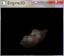
|
|
考え方は、マテリアルのアルファブレンディングとほぼ同じ。
テクスチャのアルファブレンディングには、ピクセルごとに透明度を設定できる利点がある。 透明度が設定できるテクスチャは、32bit 色だけである。 上のコードに以下の赤字部分を置換または追加する。
void Paint_Triangle(HDC hDC, LPPOLYPAINT pp);
void M_Create();

// 三角形塗り
// pply     : 三角形の頂点と色のリスト
void Paint_Triangle(HDC hDC, LPPOLYPAINT pply)
{
    EDGE        data[3];    // 頂点リスト
    EDGE        aet[2];     // アクティブ辺テーブル(AET)
    ET          et[HEIGHT]; // 辺テーブル(ET)
    int         i,j,y_min,y_max,prev,next,next2,data_ct,aet_ct,y_next;
    UINT        stride_sum;
    float       z = 0;      // Z 値
    ARGBN       argbDiffuse,argbSpecular,argbTex,argbVtx,argbBase;
    VEC2        texcrd;
    RATE        rate;

    // Y座標のクリッピング
    for(i=0; i<3; i++){
        if(pply[i].pos.y < 0)
            pply[i].pos.y = 0;
        if(pply[i].pos.y >= HEIGHT)
            pply[i].pos.y = HEIGHT - 1;
    }
    // Y座標の最大値と最小値を求める
    y_min = pply[0].pos.y;
    y_max = pply[0].pos.y;
    for(i=1; i<3; i++){
        if(pply[i].pos.y < y_min){
            y_min = pply[i].pos.y;
        }
        else if(pply[i].pos.y > y_max)
            y_max = pply[i].pos.y;
    }
    // 頂点リスト初期化
    for(i=0; i<3; i++){
        data[i].next = -1;
    }
    // ET 初期化
    for(i=y_min; i<=y_max; i++){
        et[i].index = -1;
        et[i].last = -1;
    }
    data_ct = 0;    // data の要素数
    for(i=0; i<3; i++){
        prev = i - 1;
        if(prev < 0){
            prev = 2;
        }
        next = i + 1;
        if(next >= 3){
            next = 0;
        }
        if(pply[i].pos.y < pply[prev].pos.y && pply[i].pos.y < pply[next].pos.y){
            Set_Data1(i, prev, data_ct, data, pply, et);
            Set_Data1(i, next, data_ct, data, pply, et);
        }
        else if(pply[i].pos.y > pply[prev].pos.y && pply[i].pos.y < pply[next].pos.y){
            Set_Data2(i, next, data_ct, data, pply, et);
        }
        else if(pply[i].pos.y > pply[next].pos.y && pply[i].pos.y < pply[prev].pos.y){
            Set_Data2(i, prev, data_ct, data, pply, et);
        }
        else if(pply[i].pos.y == pply[prev].pos.y && pply[i].pos.y < pply[next].pos.y){
            Set_Data1(i, next, data_ct, data, pply, et);
        }
        else if(pply[i].pos.y == pply[next].pos.y && pply[i].pos.y < pply[prev].pos.y){
            Set_Data1(i, prev, data_ct, data, pply, et);
        }
        else if(pply[i].pos.y == pply[next].pos.y && pply[i].pos.y == pply[prev].pos.y){
            Set_Data1(i, i, data_ct, data, pply, et);
        }
    }
    // スキャン・ライン・アルゴリズムによる塗り潰し
    aet_ct = 0; // AET の要素数
    stride_sum = y_min * gnStride;
    for(i=y_min; i<=y_max; i++){
        // スキャンライン上の頂点を検索
        if(et[i].index != -1){
            aet[aet_ct ++] = data[et[i].index];
            next2 = data[et[i].index].next;
            if(next2 != -1){
                aet[aet_ct ++] = data[next2];
                next2 = data[next2].next;
            }
        }
        // AET を x について昇順にソート
        if(aet[0].x > aet[1].x){
            EDGE e = aet[0];
            aet[0] = aet[1];
            aet[1] = e;
        }
        // X座標のクリッピング
        if(aet[0].x < 0){
            aet[0].x = 0;
        }
        if(aet[1].x >= WIDTH){
            aet[1].x = WIDTH - 1;
        }
        // スキャンラインの描画
        LPBYTE  pb = gpBitsWork + stride_sum + aet[0].x * COLOR_BYTE;
        for(j=aet[0].x;j<aet[1].x;j++){
            Set_ValRate(&rate, j, aet[0].x, aet[1].x);
            Set_Z(&z, &rate, aet[0].z, aet[1].z);
            if(z < gZBuf[i][j]){    // ピクセルごとの Z バッファ判定
                gZBuf[i][j] = z;
                // ディフーズ色
                Set_Color(&argbDiffuse, &rate, aet[0].color1, aet[1].color1);
                // スペキュラ色
                Set_Color(&argbSpecular, &rate, aet[0].color2, aet[1].color2);
                if(gSpecularPower > 0){
                    argbVtx = argbSpecular;
                }
                else{
                    argbVtx.a = argbVtx.r = argbVtx.g = argbVtx.b = 0;
                }
                // テクスチャ座標
                Set_TexCrd(&texcrd, &rate, aet[0].texcrd, aet[1].texcrd);
                if(texcrd.x < 0)
                    texcrd.x -= (int)(texcrd.x - 1);
                else if(texcrd.x > 1)
                    texcrd.x -= (int) texcrd.x;
                if(texcrd.y < 0)
                    texcrd.y -= (int)(texcrd.y - 1);
                else if(texcrd.y > 1)
                    texcrd.y -= (int) texcrd.y;
                // テクスチャ色
                int     xTex = (int)(texcrd.x * (gTex.width - 1));
                int     yTex = (int)(texcrd.y * (gTex.height - 1));
                DWORD   val = gTex.pBits[gTex.width * yTex + xTex];
                argbTex.a = (BYTE)(val >> 24);
                argbTex.r = (BYTE)(val >> 16);
                argbTex.g = (BYTE)(val >> 8);
                argbTex.b = (BYTE)(val);
                // テクスチャに濃淡を設定
                argbTex.r = gMultTbl[argbTex.r][argbDiffuse.r];
                argbTex.g = gMultTbl[argbTex.g][argbDiffuse.g];
                argbTex.b = gMultTbl[argbTex.b][argbDiffuse.b];
                // テクスチャにハイライトを設定
                argbVtx.r += argbTex.r;
                argbVtx.g += argbTex.g;
                argbVtx.b += argbTex.b;
                // 環境光設定
                argbVtx.r += gAmbient.r;
                argbVtx.g += gAmbient.g;
                argbVtx.b += gAmbient.b;
                if(argbVtx.r < 0)
                    argbVtx.r = 0;
                else if(argbVtx.r > 255)
                    argbVtx.r = 255;
                if(argbVtx.g < 0)
                    argbVtx.g = 0;
                else if(argbVtx.g > 255)
                    argbVtx.g = 255;
                if(argbVtx.b < 0)
                    argbVtx.b = 0;
                else if(argbVtx.b > 255)
                    argbVtx.b = 255;
                // アルファ ブレンディング
                argbVtx.a = gMultTbl[argbVtx.a][argbTex.a];
                argbBase.a = MULT2 - argbVtx.a;
                argbBase.b = *(pb + 0);
                argbBase.g = *(pb + 1);
                argbBase.r = *(pb + 2);
                argbVtx.r = gMultTbl[argbVtx.r][argbVtx.a] + gMultTbl[argbBase.r][argbBase.a];
                argbVtx.g = gMultTbl[argbVtx.g][argbVtx.a] + gMultTbl[argbBase.g][argbBase.a];
                argbVtx.b = gMultTbl[argbVtx.b][argbVtx.a] + gMultTbl[argbBase.b][argbBase.a];
                // ピクセル値設定
                *pb ++ = (BYTE) argbVtx.b;
                *pb ++ = (BYTE) argbVtx.g;
                *pb ++ = (BYTE) argbVtx.r;
            }
            else{
                pb += COLOR_BYTE;
            }
        }
        stride_sum += gnStride;
        // i == y_max の要素を AET から削除
        if(i == aet[1].y_max){
            aet_ct --;
        }
        if(i == aet[0].y_max){
            aet[0] = aet[1];
            aet_ct --;
        }
        // AET の各 x を次のスキャンラインでの値に更新
        for(j=0;j<2;j++){
            y_next = i + 1;
            aet[j].x = Round(aet[j].x_min + aet[j].slant_sum);
            aet[j].slant_sum += aet[j].slant;
            Set_ValRate(&rate, y_next, aet[j].y_min, aet[j].y_max);
            Set_Color(&aet[j].color1, &rate, aet[j].c1_min, aet[j].c1_max);
            Set_Color(&aet[j].color2, &rate, aet[j].c2_min, aet[j].c2_max);
            Set_Z(&aet[j].z, &rate, aet[j].z_min, aet[j].z_max);
            Set_TexCrd(&aet[j].texcrd, &rate, aet[j].t_min, aet[j].t_max);
        }
    }
}// Paint_Triangle

// 初期化
void M_Create()
{
    // 立方体作成
    Create_Cube();
    // 面・頂点法線ベクトル設定
    Set_Normal();
    // 掛け算対応表作成
    int i,j;
    for(i=0; i<=MULT1; i++){
        for(j=0; j<=MULT2; j++){
            gMultTbl[i][j] = ((i * j) / MULT2);
        }
    }
    // テクスチャ ファイル
    BITMAP      bmp;
    BITMAPINFO  bi;
    char        *p;
    char        path[MAX_PATH];
    GetModuleFileName(NULL, path, sizeof(path));
    p = strrchr(path, '\\');
    strcpy(p+1, "tex2.bmp");
    HBITMAP hBmp = (HBITMAP) LoadImage(NULL, path, IMAGE_BITMAP, 0, 0, LR_LOADFROMFILE|LR_CREATEDIBSECTION);
    GetObject(hBmp, sizeof(bmp), &bmp);
    ZeroMemory(&bi, sizeof(bi));
    bi.bmiHeader.biSize         = sizeof(BITMAPINFOHEADER);
    bi.bmiHeader.biWidth        = bmp.bmWidth;
    bi.bmiHeader.biHeight       = - bmp.bmHeight;
    bi.bmiHeader.biPlanes       = 1;
    bi.bmiHeader.biBitCount     = 32;
    bi.bmiHeader.biCompression  = BI_RGB;
    gTex.hBmp = (HBITMAP) CreateDIBSection(NULL, &bi, DIB_RGB_COLORS, (VOID**) &gTex.pBits, NULL, 0);
    HDC  hdcCp1,hdcCp2;
    HBITMAP hbmOld1,hbmOld2;
    hdcCp1 = CreateCompatibleDC(NULL);
    hdcCp2 = CreateCompatibleDC(NULL);
    hbmOld1 = (HBITMAP)SelectObject(hdcCp1, gTex.hBmp);
    hbmOld2 = (HBITMAP)SelectObject(hdcCp2, hBmp);
    BitBlt(hdcCp1, 0, 0, bmp.bmWidth, bmp.bmHeight, hdcCp2, 0, 0, SRCCOPY);
    SelectObject(hdcCp1, hbmOld1);
    SelectObject(hdcCp2, hbmOld2);
    DeleteDC(hdcCp1);
    DeleteDC(hdcCp2);
    DeleteObject(hBmp);
    gTex.width  = bmp.bmWidth;
    gTex.height = bmp.bmHeight;
    gTex.stride = WIDTHBYTES(bi.bmiHeader.biWidth * bi.bmiHeader.biBitCount);
    // 24bpp 以下の場合は透明度に 255 を設定
    if(bmp.bmBitsPixel <= 24){
        int size;
        size = gTex.width * gTex.height;
        PBYTE   pb = (PBYTE) gTex.pBits + 3;
        for(i = 0; i < size; i++){
            *pb = MULT2;
            pb += 4;
        }
    }
}// M_Create
|
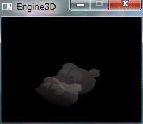
|
|
遠くのピクセルほどフォグ色に近くする。
考え方は、アルファブレンディングに近い。 上のコードに以下の赤字部分を追加する。 参考資料:Microsoft DirectX9 ヘルプ typedef struct{ float z_near; // 視点に最も近いフォグ Z 位置 float z_far; // 視点から最も遠いフォグ Z 位置 RGBB color; // フォグ色 }FOG,*LPFOG; FOG gFog; void Paint_Triangle(HDC hDC, LPPOLYPAINT pp); void M_Create(); void M_Paint(HDC hDC); // 三角形塗り // pply : 三角形の頂点と色のリスト void Paint_Triangle(HDC hDC, LPPOLYPAINT pply) { EDGE data[3]; // 頂点リスト EDGE aet[2]; // アクティブ辺テーブル(AET) ET et[HEIGHT]; // 辺テーブル(ET) int i,j,y_min,y_max,prev,next,next2,data_ct,aet_ct,y_next; UINT stride_sum; float z = 0; // Z 値 ARGBN argbDiffuse,argbSpecular,argbTex,argbVtx,argbBase; VEC2 texcrd; RATE rate; // Y座標のクリッピング for(i=0; i<3; i++){ if(pply[i].pos.y < 0) pply[i].pos.y = 0; if(pply[i].pos.y >= HEIGHT) pply[i].pos.y = HEIGHT - 1; } // Y座標の最大値と最小値を求める y_min = pply[0].pos.y; y_max = pply[0].pos.y; for(i=1; i<3; i++){ if(pply[i].pos.y < y_min){ y_min = pply[i].pos.y; } else if(pply[i].pos.y > y_max) y_max = pply[i].pos.y; } // 頂点リスト初期化 for(i=0; i<3; i++){ data[i].next = -1; } // ET 初期化 for(i=y_min; i<=y_max; i++){ et[i].index = -1; et[i].last = -1; } data_ct = 0; // data の要素数 for(i=0; i<3; i++){ prev = i - 1; if(prev < 0){ prev = 2; } next = i + 1; if(next >= 3){ next = 0; } if(pply[i].pos.y < pply[prev].pos.y && pply[i].pos.y < pply[next].pos.y){ Set_Data1(i, prev, data_ct, data, pply, et); Set_Data1(i, next, data_ct, data, pply, et); } else if(pply[i].pos.y > pply[prev].pos.y && pply[i].pos.y < pply[next].pos.y){ Set_Data2(i, next, data_ct, data, pply, et); } else if(pply[i].pos.y > pply[next].pos.y && pply[i].pos.y < pply[prev].pos.y){ Set_Data2(i, prev, data_ct, data, pply, et); } else if(pply[i].pos.y == pply[prev].pos.y && pply[i].pos.y < pply[next].pos.y){ Set_Data1(i, next, data_ct, data, pply, et); } else if(pply[i].pos.y == pply[next].pos.y && pply[i].pos.y < pply[prev].pos.y){ Set_Data1(i, prev, data_ct, data, pply, et); } else if(pply[i].pos.y == pply[next].pos.y && pply[i].pos.y == pply[prev].pos.y){ Set_Data1(i, i, data_ct, data, pply, et); } } // スキャン・ライン・アルゴリズムによる塗り潰し aet_ct = 0; // AET の要素数 stride_sum = y_min * gnStride; for(i=y_min; i<=y_max; i++){ // スキャンライン上の頂点を検索 if(et[i].index != -1){ aet[aet_ct ++] = data[et[i].index]; next2 = data[et[i].index].next; if(next2 != -1){ aet[aet_ct ++] = data[next2]; next2 = data[next2].next; } } // AET を x について昇順にソート if(aet[0].x > aet[1].x){ EDGE e = aet[0]; aet[0] = aet[1]; aet[1] = e; } // X座標のクリッピング if(aet[0].x < 0){ aet[0].x = 0; } if(aet[1].x >= WIDTH){ aet[1].x = WIDTH - 1; } // スキャンラインの描画 LPBYTE pb = gpBitsWork + stride_sum + aet[0].x * COLOR_BYTE; for(j=aet[0].x;j<aet[1].x;j++){ Set_ValRate(&rate, j, aet[0].x, aet[1].x); Set_Z(&z, &rate, aet[0].z, aet[1].z); if(z < gZBuf[i][j]){ // ピクセルごとの Z バッファ判定 gZBuf[i][j] = z; // ディフーズ色 Set_Color(&argbDiffuse, &rate, aet[0].color1, aet[1].color1); // スペキュラ色 Set_Color(&argbSpecular, &rate, aet[0].color2, aet[1].color2); if(gSpecularPower > 0){ argbVtx = argbSpecular; } else{ argbVtx.a = argbVtx.r = argbVtx.g = argbVtx.b = 0; } // テクスチャ座標 Set_TexCrd(&texcrd, &rate, aet[0].texcrd, aet[1].texcrd); if(texcrd.x < 0) texcrd.x -= (int)(texcrd.x - 1); else if(texcrd.x > 1) texcrd.x -= (int) texcrd.x; if(texcrd.y < 0) texcrd.y -= (int)(texcrd.y - 1); else if(texcrd.y > 1) texcrd.y -= (int) texcrd.y; // テクスチャ色 int xTex = (int)(texcrd.x * (gTex.width - 1)); int yTex = (int)(texcrd.y * (gTex.height - 1)); DWORD val = gTex.pBits[gTex.width * yTex + xTex]; argbTex.a = (BYTE)(val >> 24); argbTex.r = (BYTE)(val >> 16); argbTex.g = (BYTE)(val >> 8); argbTex.b = (BYTE)(val); // テクスチャに濃淡を設定 argbTex.r = gMultTbl[argbTex.r][argbDiffuse.r]; argbTex.g = gMultTbl[argbTex.g][argbDiffuse.g]; argbTex.b = gMultTbl[argbTex.b][argbDiffuse.b]; // テクスチャにハイライトを設定 argbVtx.r += argbTex.r; argbVtx.g += argbTex.g; argbVtx.b += argbTex.b; // 環境光設定 argbVtx.r += gAmbient.r; argbVtx.g += gAmbient.g; argbVtx.b += gAmbient.b; if(argbVtx.r < 0) argbVtx.r = 0; else if(argbVtx.r > 255) argbVtx.r = 255; if(argbVtx.g < 0) argbVtx.g = 0; else if(argbVtx.g > 255) argbVtx.g = 255; if(argbVtx.b < 0) argbVtx.b = 0; else if(argbVtx.b > 255) argbVtx.b = 255; // フォグ int n1; if(gFog.z_far != gFog.z_near) n1 = (int)((gFog.z_far - z) * MULT2 / (gFog.z_far - gFog.z_near)); else n1 = 1; if(n1 < 0) n1 = -n1; else if(n1 > MULT2) n1 = MULT2; int n2 = MULT2 - n1; argbVtx.r = (BYTE)(gMultTbl[argbVtx.r][n1] + gMultTbl[gFog.color.r][n2]); argbVtx.g = (BYTE)(gMultTbl[argbVtx.g][n1] + gMultTbl[gFog.color.g][n2]); argbVtx.b = (BYTE)(gMultTbl[argbVtx.b][n1] + gMultTbl[gFog.color.b][n2]); // アルファ ブレンディング argbVtx.a = gMultTbl[argbVtx.a][argbTex.a]; argbBase.a = MULT2 - argbVtx.a; argbBase.b = *(pb + 0); argbBase.g = *(pb + 1); argbBase.r = *(pb + 2); argbVtx.r = gMultTbl[argbVtx.r][argbVtx.a] + gMultTbl[argbBase.r][argbBase.a]; argbVtx.g = gMultTbl[argbVtx.g][argbVtx.a] + gMultTbl[argbBase.g][argbBase.a]; argbVtx.b = gMultTbl[argbVtx.b][argbVtx.a] + gMultTbl[argbBase.b][argbBase.a]; // ピクセル値設定 *pb ++ = (BYTE) argbVtx.b; *pb ++ = (BYTE) argbVtx.g; *pb ++ = (BYTE) argbVtx.r; } else{ pb += COLOR_BYTE; } } stride_sum += gnStride; // i == y_max の要素を AET から削除 if(i == aet[1].y_max){ aet_ct --; } if(i == aet[0].y_max){ aet[0] = aet[1]; aet_ct --; } // AET の各 x を次のスキャンラインでの値に更新 for(j=0;j<2;j++){ y_next = i + 1; aet[j].x = Round(aet[j].x_min + aet[j].slant_sum); aet[j].slant_sum += aet[j].slant; Set_ValRate(&rate, y_next, aet[j].y_min, aet[j].y_max); Set_Color(&aet[j].color1, &rate, aet[j].c1_min, aet[j].c1_max); Set_Color(&aet[j].color2, &rate, aet[j].c2_min, aet[j].c2_max); Set_Z(&aet[j].z, &rate, aet[j].z_min, aet[j].z_max); Set_TexCrd(&aet[j].texcrd, &rate, aet[j].t_min, aet[j].t_max); } } }// Paint_Triangle // 初期化 void M_Create() { // 立方体作成 Create_Cube(); // 面・頂点法線ベクトル設定 Set_Normal(); // 掛け算対応表作成 int i,j; for(i=0; i<=MULT1; i++){ for(j=0; j<=MULT2; j++){ gMultTbl[i][j] = ((i * j) / MULT2); } } // テクスチャ ファイル BITMAP bmp; BITMAPINFO bi; char *p; char path[MAX_PATH]; GetModuleFileName(NULL, path, sizeof(path)); p = strrchr(path, '\\'); strcpy(p+1, "tex2.bmp"); HBITMAP hBmp = (HBITMAP) LoadImage(NULL, path, IMAGE_BITMAP, 0, 0, LR_LOADFROMFILE|LR_CREATEDIBSECTION); GetObject(hBmp, sizeof(bmp), &bmp); ZeroMemory(&bi, sizeof(bi)); bi.bmiHeader.biSize = sizeof(BITMAPINFOHEADER); bi.bmiHeader.biWidth = bmp.bmWidth; bi.bmiHeader.biHeight = - bmp.bmHeight; bi.bmiHeader.biPlanes = 1; bi.bmiHeader.biBitCount = 32; bi.bmiHeader.biCompression = BI_RGB; gTex.hBmp = (HBITMAP) CreateDIBSection(NULL, &bi, DIB_RGB_COLORS, (VOID**) &gTex.pBits, NULL, 0); HDC hdcCp1,hdcCp2; HBITMAP hbmOld1,hbmOld2; hdcCp1 = CreateCompatibleDC(NULL); hdcCp2 = CreateCompatibleDC(NULL); hbmOld1 = (HBITMAP)SelectObject(hdcCp1, gTex.hBmp); hbmOld2 = (HBITMAP)SelectObject(hdcCp2, hBmp); BitBlt(hdcCp1, 0, 0, bmp.bmWidth, bmp.bmHeight, hdcCp2, 0, 0, SRCCOPY); SelectObject(hdcCp1, hbmOld1); SelectObject(hdcCp2, hbmOld2); DeleteDC(hdcCp1); DeleteDC(hdcCp2); DeleteObject(hBmp); gTex.width = bmp.bmWidth; gTex.height = bmp.bmHeight; gTex.stride = WIDTHBYTES(bi.bmiHeader.biWidth * bi.bmiHeader.biBitCount); // 24bpp 以下の場合は透明度に 255 を設定 if(bmp.bmBitsPixel <= 24){ int size; size = gTex.width * gTex.height; PBYTE pb = (PBYTE) gTex.pBits + 3; for(i = 0; i < size; i++){ *pb = MULT2; pb += 4; } } // フォグ情報設定 gFog.z_near = gZFar - 0.4f; gFog.z_far = gZFar; gFog.color.r = gFog.color.g = gFog.color.b = 128; }// M_Create // 描画 void M_Paint(HDC hDC) { const VEC3 pos_look = {0.0f, 0.0f, -2.0f}; // 視点の位置 const VEC3 pos_lookat = {0.0f, 0.0f, 0.0f}; // 注視点の位置 const VEC3 v_lookup = {0, 1, 0}; // 視点の上向き VEC3 v_sun = {0.0f, -1.0f, 1.0f}; // 入射光のベクトル const RGBB material = {255, 255, 255}; // 面のディフューズ色(各色 0 〜 255) const RGBB ambient = {10, 10, 10}; // 環境光(各色 0 〜 255) MTRX mtScal,mtRotY,mtTrans,mtWork; static int roll_y = 0; // 回転角度 // 行列設定 gMtView = MtrxView(pos_look, pos_lookat, v_lookup); gMtProj = MtrxPerspect(0.0f, 10.0f, 3.14f / 4, 1.0f); // gMtProj = MtrxOrtho(0.0f, 10.0f, 5.0f, 5.0f); // 入射光ベクトル v_sun.x = - v_sun.x; v_sun.y = - v_sun.y; v_sun.z = - v_sun.z; v_sun = Vec3Normalize(v_sun); // Zバッファ初期化 Clear_ZBuf(); // オブジェクト描画 mtScal = MtrxScal(1.0f, 1.0f, 1.0f); mtRotY = MtrxRotY(roll_y * 3.14f / 180); mtWork = MtrxMult(mtScal, mtRotY); mtTrans = MtrxTranslate(-0.2f, 0.2f, 0.0f); gMtWorld = MtrxMult(mtWork, mtTrans); Draw_Cube(hDC, v_sun); mtTrans = MtrxTranslate(0.2f, 0.0f,-1.0f); gMtWorld = MtrxMult(mtWork, mtTrans); Draw_Cube(hDC, v_sun); // 回転角度増 roll_y += 10; if(roll_y >= 360) roll_y = 0; }// M_Paint |
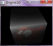
|
|
これまでは、面単位のライティングであるグーローシェーディングを使ってきたが、
ピクセル単位のライティングに変更すると、少ないポリゴン数でも多くのポリゴンを 使ったような高品質のレンダリング結果が得られる。 ただし、ライティング計算回数が増えるため、オーバーヘッドが高くなる。 テクスチャ表示のコードに以下の赤字部分を置換または追加する。 参考資料:コンピュータ・グラフィックス J.D.FOLEY/A.VAN DAM著 日本コンピュータ協会 typedef struct{ BYTE a; BYTE r; BYTE g; BYTE b; }ARGBB,*LPARGBB; typedef struct{ POINT pos; // 頂点座標 VEC3 n; // 頂点法線ベクトル float z; // 頂点Z値 D3DXVECTOR2 t; // テクスチャ座標 }POLYPAINT,*LPPOLYPAINT; typedef struct{ int y_min; // 辺の最小Y座標 int y_max; // 辺の最大Y座標 int x_min; // 辺の最小Y座標のX座標 int x; // スキャンラインと辺の交点のX座標 double slant; // 辺の傾きの逆数の整数部 double slant_sum; // slantの和 VEC3 n_min; // 辺の最小Y座標の頂点法線ベクトル VEC3 n_max; // 辺の最大Y座標の頂点法線ベクトル VEC3 normal; // 頂点法線ベクトル float z_min; // 辺の最小Y座標のZ値 float z_max; // 辺の最大Y座標のZ値 float z; // Z値 D3DXVECTOR2 t_min; // 辺の最小Y座標のテクスチャ座標 D3DXVECTOR2 t_max; // 辺の最大Y座標のテクスチャ座標 D3DXVECTOR2 texcrd; // テクスチャ座標 int next; // 次のデータ番号 }EDGE,*LPEDGE; float d_perspect = HEIGHT; // 透視投象での投影するスクリーンと視点の距離 POINT offset = {WIDTH / 2, HEIGHT / 2}; // 投象後の二次元座標の平行移動幅 float power1 = 0.7f; // 反射の強さ(0 〜 1) int specular_power = 3; // スペキュラ反射の強さ ARGBB diffuse = {128, 255, 255, 255}; // 面のディフューズ色(各色 0 〜 255) ARGBB specular = {255, 255, 255, 255}; // 面のスペキュラ色(各色 0 〜 255) RGBB ambient = {10, 10, 10}; // 環境光(各色 0 〜 255) void Draw_Cube(HDC hDC, VEC3 v_sun); void Paint_Triangle(HDC hDC, LPPOLYPAINT pp, VEC3 v_sun); void Set_Data1(int idx_min, int idx_max, int &data_ct, LPEDGE data, LPPOLYPAINT pply, LPET et); void Set_Data2(int idx_min, int idx_max, int &data_ct, LPEDGE data, LPPOLYPAINT pply, LPET et); void Set_Vector(LPVEC3 vector, LPRATE rate, VEC3 v_min, VEC3 v_max); void M_Paint(HDC hDC); // 立方体描画 void Draw_Cube(HDC hDC, VEC3 v_sun) { int i,j; VEC3 v_wv[4],v_all[4]; VEC3 v_look; // 注視点から視点へのベクトル POLYPAINT ply1[4]; // 4頂点ポリゴン色塗り情報 POLYPAINT ply2[2][3]; // 3頂点ポリゴン色塗り情報 gMtWorldView = MtrxMult(gMtWorld, gMtView); gMtAll = MtrxMult(gMtWorldView, gMtProj); // 視線ベクトル VEC3 posLookAt = MtrxVec3(gPosLookAt, gMtWorld); v_look = Vec3Normalize(MtrxVec3(Vec3Sub(posLookAt, gPosLook), gMtView)); for(i=0; i<6; i++){ for(j=0; j<4; j++){ int index = gmCube.f[i][j]; // 頂点のワールド・ビュー行列変換 v_wv[j] = Vec3Normalize(MtrxVec3(gmCube.v[index], gMtWorldView)); } // 面法線ベクトル計算(カリング用) VEC3 fn_cull = Get_FaceNormal(v_wv); // カリング float dot_cull = Vec3Dot(v_look, fn_cull); if(dot_cull < 0){ // 片面表示 for(j=0; j<4; j++){ int index = gmCube.f[i][j]; // 頂点のワールド・ビュー・プロジェクション行列変換 v_all[j] = MtrxVec3(gmCube.v[index], gMtAll); // 頂点法線ベクトルのワールド行列変換 VEC3 n_color; n_color = MtrxVec3(gmCube.n[index], gMtWorld); n_color = Vec3Normalize(n_color); float size_rate = d_perspect; if(gFlagPerspect) size_rate /= (v_all[j].z + gPosLookAt.z - gPosLook.z); ply1[j].pos.x = (long)( v_all[j].x * size_rate + offset.x); ply1[j].pos.y = (long)(-v_all[j].y * size_rate + offset.y); ply1[j].z = v_all[j].z; ply1[j].n = n_color; ply1[j].t = gmCube.t[index]; } ply2[0][0] = ply1[0]; ply2[0][1] = ply1[1]; ply2[0][2] = ply1[2]; ply2[1][0] = ply1[0]; ply2[1][1] = ply1[2]; ply2[1][2] = ply1[3]; Paint_Triangle(hDC, ply2[0], v_sun); Paint_Triangle(hDC, ply2[1], v_sun); } } }// Draw_Cube // 三角形塗り // pply : 三角形の頂点と色のリスト void Paint_Triangle(HDC hDC, LPPOLYPAINT pply, VEC3 v_sun) { EDGE data[3]; // 頂点リスト EDGE aet[2]; // アクティブ辺テーブル(AET) ET et[HEIGHT]; // 辺テーブル(ET) int i,j,y_min,y_max,prev,next,next2,data_ct,aet_ct,y_next; UINT stride_sum; float z = 0; // Z 値 ARGBN argbLight,argbTex,argbVtx,argbBase; VEC2 texcrd; VEC3 normal; RATE rate; float power2,powerSpecular,powerDiffuse; // Y座標のクリッピング for(i=0; i<3; i++){ if(pply[i].pos.y < 0) pply[i].pos.y = 0; if(pply[i].pos.y >= HEIGHT) pply[i].pos.y = HEIGHT - 1; } // Y座標の最大値と最小値を求める y_min = pply[0].pos.y; y_max = pply[0].pos.y; for(i=1; i<3; i++){ if(pply[i].pos.y < y_min){ y_min = pply[i].pos.y; } else if(pply[i].pos.y > y_max) y_max = pply[i].pos.y; } // 頂点リスト初期化 for(i=0; i<3; i++){ data[i].next = -1; } // ET 初期化 for(i=y_min; i<=y_max; i++){ et[i].index = -1; et[i].last = -1; } data_ct = 0; // data の要素数 for(i=0; i<3; i++){ prev = i - 1; if(prev < 0){ prev = 2; } next = i + 1; if(next >= 3){ next = 0; } if(pply[i].pos.y < pply[prev].pos.y && pply[i].pos.y < pply[next].pos.y){ Set_Data1(i, prev, data_ct, data, pply, et); Set_Data1(i, next, data_ct, data, pply, et); } else if(pply[i].pos.y > pply[prev].pos.y && pply[i].pos.y < pply[next].pos.y){ Set_Data2(i, next, data_ct, data, pply, et); } else if(pply[i].pos.y > pply[next].pos.y && pply[i].pos.y < pply[prev].pos.y){ Set_Data2(i, prev, data_ct, data, pply, et); } else if(pply[i].pos.y == pply[prev].pos.y && pply[i].pos.y < pply[next].pos.y){ Set_Data1(i, next, data_ct, data, pply, et); } else if(pply[i].pos.y == pply[next].pos.y && pply[i].pos.y < pply[prev].pos.y){ Set_Data1(i, prev, data_ct, data, pply, et); } else if(pply[i].pos.y == pply[next].pos.y && pply[i].pos.y == pply[prev].pos.y){ Set_Data1(i, i, data_ct, data, pply, et); } } // スキャン・ライン・アルゴリズムによる塗り潰し aet_ct = 0; // AET の要素数 stride_sum = y_min * gnStride; for(i=y_min; i<=y_max; i++){ // スキャンライン上の頂点を検索 if(et[i].index != -1){ aet[aet_ct ++] = data[et[i].index]; next2 = data[et[i].index].next; if(next2 != -1){ aet[aet_ct ++] = data[next2]; next2 = data[next2].next; } } // AET を x について昇順にソート if(aet[0].x > aet[1].x){ EDGE e = aet[0]; aet[0] = aet[1]; aet[1] = e; } // X座標のクリッピング if(aet[0].x < 0){ aet[0].x = 0; } if(aet[1].x >= WIDTH){ aet[1].x = WIDTH - 1; } // スキャンラインの描画 LPBYTE pb = gpBitsWork + stride_sum + aet[0].x * COLOR_BYTE; for(j=aet[0].x;j<aet[1].x;j++){ Set_ValRate(&rate, j, aet[0].x, aet[1].x); Set_Z(&z, &rate, aet[0].z, aet[1].z); if(z < gZBuf[i][j]){ // ピクセルごとの Z バッファ判定 gZBuf[i][j] = z; // 照明色 Set_Vector(&normal, &rate, aet[0].normal, aet[1].normal); power2 = Vec3Dot(v_sun, normal); powerDiffuse = power1 * power2; if(powerDiffuse < 0){ powerDiffuse = 0; } argbLight.a = diffuse.a; argbLight.r = (UINT)(diffuse.r * powerDiffuse); argbLight.g = (UINT)(diffuse.g * powerDiffuse); argbLight.b = (UINT)(diffuse.b * powerDiffuse); if(argbLight.r > 255) argbLight.r = 255; if(argbLight.g > 255) argbLight.g = 255; if(argbLight.b > 255) argbLight.b = 255; if(specular_power > 0){ powerSpecular = power1 * (float) pow(power2, (int) specular_power); if(powerSpecular < 0){ powerSpecular = 0; } argbVtx.a = diffuse.a; argbVtx.r = (UINT)(specular.r * powerSpecular); argbVtx.g = (UINT)(specular.g * powerSpecular); argbVtx.b = (UINT)(specular.b * powerSpecular); if(argbVtx.r > 255) argbVtx.r = 255; if(argbVtx.g > 255) argbVtx.g = 255; if(argbVtx.b > 255) argbVtx.b = 255; } // テクスチャ座標 Set_TexCrd(&texcrd, &rate, aet[0].texcrd, aet[1].texcrd); if(texcrd.x < 0) texcrd.x -= (int)(texcrd.x - 1); else if(texcrd.x > 1) texcrd.x -= (int) texcrd.x; if(texcrd.y < 0) texcrd.y -= (int)(texcrd.y - 1); else if(texcrd.y > 1) texcrd.y -= (int) texcrd.y; // テクスチャ色 int xTex = (int)(texcrd.x * (gTex.width - 1)); int yTex = (int)(texcrd.y * (gTex.height - 1)); DWORD val = gTex.pBits[gTex.width * yTex + xTex]; argbTex.r = (BYTE)(val >> 16); argbTex.g = (BYTE)(val >> 8); argbTex.b = (BYTE)(val); // テクスチャに濃淡を設定 argbTex.r = gMultTbl[argbTex.r][argbLight.r]; argbTex.g = gMultTbl[argbTex.g][argbLight.g]; argbTex.b = gMultTbl[argbTex.b][argbLight.b]; // テクスチャにハイライトを設定 argbVtx.r += argbTex.r; argbVtx.g += argbTex.g; argbVtx.b += argbTex.b; // 環境光設定 argbVtx.r += gAmbient.r; argbVtx.g += gAmbient.g; argbVtx.b += gAmbient.b; if(argbVtx.r < 0) argbVtx.r = 0; else if(argbVtx.r > 255) argbVtx.r = 255; if(argbVtx.g < 0) argbVtx.g = 0; else if(argbVtx.g > 255) argbVtx.g = 255; if(argbVtx.b < 0) argbVtx.b = 0; else if(argbVtx.b > 255) argbVtx.b = 255; // ピクセル値設定 *pb ++ = (BYTE) argbVtx.b; *pb ++ = (BYTE) argbVtx.g; *pb ++ = (BYTE) argbVtx.r; } else{ pb += COLOR_BYTE; } } stride_sum += gnStride; // i == y_max の要素を AET から削除 if(i == aet[1].y_max){ aet_ct --; } if(i == aet[0].y_max){ aet[0] = aet[1]; aet_ct --; } // AET の各 x を次のスキャンラインでの値に更新 for(j=0;j<2;j++){ y_next = i + 1; aet[j].x = Round(aet[j].x_min + aet[j].slant_sum); aet[j].slant_sum += aet[j].slant; Set_ValRate(&rate, y_next, aet[j].y_min, aet[j].y_max); Set_Vector(&aet[j].normal, &rate, aet[j].n_min, aet[j].n_max); Set_Z(&aet[j].z, &rate, aet[j].z_min, aet[j].z_max); Set_TexCrd(&aet[j].texcrd, &rate, aet[j].t_min, aet[j].t_max); } } }// Paint_Triangle // 頂点リスト設定1 void Set_Data1(int idx_min, int idx_max, int &data_ct, LPEDGE data, LPPOLYPAINT pply, LPET et) { int et_idx = pply[idx_min].pos.y; if(et[et_idx].last == -1) et[et_idx].index = data_ct; else data[et[et_idx].last].next = data_ct; et[et_idx].last = data_ct; data[data_ct].y_min = pply[idx_min].pos.y; data[data_ct].y_max = pply[idx_max].pos.y; data[data_ct].x_min = pply[idx_min].pos.x; data[data_ct].x = data[data_ct].x_min; data[data_ct].slant = (double)(pply[idx_max].pos.x - pply[idx_min].pos.x) / (pply[idx_max].pos.y - pply[idx_min].pos.y); data[data_ct].slant_sum = data[data_ct].slant; data[data_ct].n_min = pply[idx_min].n; data[data_ct].n_max = pply[idx_max].n; data[data_ct].normal = data[data_ct].n_min; data[data_ct].z_min = pply[idx_min].z; data[data_ct].z_max = pply[idx_max].z; data[data_ct].z = data[data_ct].z_min; data[data_ct].t_min = pply[idx_min].t; data[data_ct].t_max = pply[idx_max].t; data[data_ct].texcrd = data[data_ct].t_min; data_ct ++; }// Set_Data1 // 頂点リスト設定2 void Set_Data2(int idx_min, int idx_max, int &data_ct, LPEDGE data, LPPOLYPAINT pply, LPET et) { int et_idx = pply[idx_min].pos.y + 1; if(et[et_idx].last == -1) et[et_idx].index = data_ct; else data[et[et_idx].last].next = data_ct; et[et_idx].last = data_ct; double slant = (double)(pply[idx_max].pos.x - pply[idx_min].pos.x) / (pply[idx_max].pos.y - pply[idx_min].pos.y); RATE rate; VEC2 texcrd; float z; VEC3 normal; Set_ValRate(&rate, et_idx, pply[idx_min].pos.y, pply[idx_max].pos.y); data[data_ct].y_min = pply[idx_min].pos.y; data[data_ct].y_max = pply[idx_max].pos.y; data[data_ct].x_min = pply[idx_min].pos.x; data[data_ct].x = Round(data[data_ct].x_min + slant); data[data_ct].slant = slant; data[data_ct].slant_sum = data[data_ct].slant + slant; Set_Vector(&normal, &rate, pply[idx_min].n, pply[idx_max].n); data[data_ct].n_min = pply[idx_min].n; data[data_ct].n_max = pply[idx_max].n; data[data_ct].normal = normal; Set_Z(&z, &rate, pply[idx_min].z, pply[idx_max].z); data[data_ct].z_min = pply[idx_min].z; data[data_ct].z_max = pply[idx_max].z; data[data_ct].z = z; Set_TexCrd(&texcrd, &rate, pply[idx_min].t, pply[idx_max].t); data[data_ct].t_min = pply[idx_min].t; data[data_ct].t_max = pply[idx_max].t; data[data_ct].texcrd = texcrd; data_ct ++; }// Set_Data2 // ベクトル設定 void Set_Vector(LPVEC3 vector, LPRATE rate, VEC3 v_min, VEC3 v_max) { if(rate->f1 != -1){ vector->x = v_max.x * rate->f1 + v_min.x * rate->f2; vector->y = v_max.y * rate->f1 + v_min.y * rate->f2; vector->z = v_max.z * rate->f1 + v_min.z * rate->f2; } else{ *vector = v_min; } }// Set_Vector // 描画 void M_Paint(HDC hDC) { const VEC3 pos_look = {0.0f, 2.0f, -2.0f}; // 視点の位置 const VEC3 pos_lookat = {0.0f, 0.0f, 0.0f}; // 注視点の位置 const VEC3 v_lookup = {0, 1, 0}; // 視点の上向き VEC3 v_sun = {0.0f, -1.0f, 1.0f}; // 入射光のベクトル MTRX mtScal,mtRotY,mtTrans,mtWork; static int roll_y = 0; // 回転角度 // 行列設定 gMtView = MtrxView(pos_look, pos_lookat, v_lookup); gMtProj = MtrxPerspect(0.0f, 10.0f, 3.14f / 4, 1.0f); // gMtProj = MtrxOrtho(0.0f, 10.0f, 5.0f, 5.0f); // 入射光ベクトル v_sun.x = - v_sun.x; v_sun.y = - v_sun.y; v_sun.z = - v_sun.z; v_sun = Vec3Normalize(v_sun); // Zバッファ初期化 Clear_ZBuf(); // オブジェクト描画 mtScal = MtrxScal(1.0f, 1.0f, 1.0f); mtRotY = MtrxRotY(roll_y * 3.14f / 180); mtWork = MtrxMult(mtScal, mtRotY); mtTrans = MtrxTranslate(-0.2f, 0.2f, 0.0f); gMtWorld = MtrxMult(mtWork, mtTrans); Draw_Cube(hDC, v_sun); mtTrans = MtrxTranslate(0.2f, 0.0f,-0.2f); gMtWorld = MtrxMult(mtWork, mtTrans); Draw_Cube(hDC, v_sun); // 回転角度増 roll_y += 10; if(roll_y >= 360) roll_y = 0; }// M_Paint |
|
|
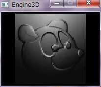

|
|
|
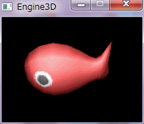
|
|
|
|
|